Method for determining amplitude of stick-slip on a valve assembly and implementation thereof

a technology of amplitude and stick-slip, which is applied in the field of data processing, can solve the problems of valve assembly, valve stem movement to improper positions, valve assembly cycle, etc., and achieve the effect of disrupting the stability of the process lin

Active Publication Date: 2015-10-01
DRESSER LLC
View PDF10 Cites 3 Cited by
  • Summary
  • Abstract
  • Description
  • Claims
  • Application Information

AI Technical Summary

Benefits of technology

[0005]The process control system will attempt to correct this error. In response to overshoot, for example, the process control system often issues instructions for the valve assembly to modulate the valve stem in the opposite direction. However, it is likely that stick-slip will disrupt the movement in the opposite ...

Problems solved by technology

From the device level, the valve assembly may suffer from improperly tuned components (e.g., valve positioner) and/or have some type of physical problem that can cause cycling to occur on the valve assembly.
Improper tuning (and calibration) of the valve positioner, for example, may translate the setpoint instructions into the pneumatic signal incorrectly and, thus, cause the valve stem to move to improper positions.
On the other hand, physical problems can frustrate operation of the mechanical components on the valve assembly.
During operation, however, stick-slip can cause internal force, i.e., pressure on the closure member, to exce...

Method used


Image

  • Method for determining amplitude of stick-slip on a valve assembly and implementation thereof
  • Method for determining amplitude of stick-slip on a valve assembly and implementation thereof
  • Method for determining amplitude of stick-slip on a valve assembly and implementation thereof

Examples


Embodiment Construction

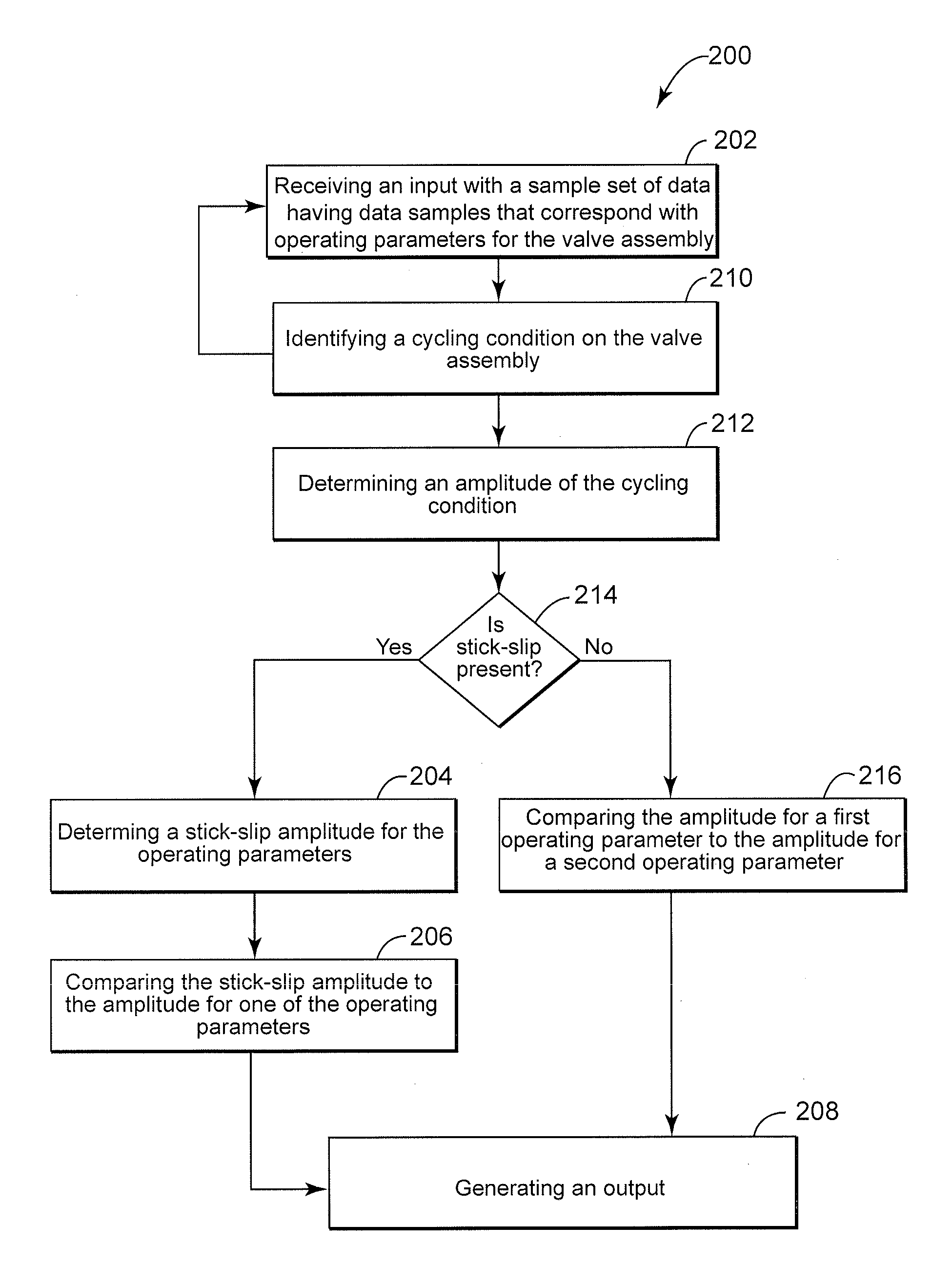
[0018]The discussion below offers a solution to determine the root cause of operating conditions on a valve assembly. Unlike previous techniques, which for the most part only detect or establish the “presence” of the operating condition, the embodiments herein can readily identify what is causing the operating condition to occur on the valve assembly. This information can enlighten the process owner / operator to better address the operating condition, effectively saving time and money by avoiding unnecessary repairs to valve assemblies that would not otherwise require maintenance.

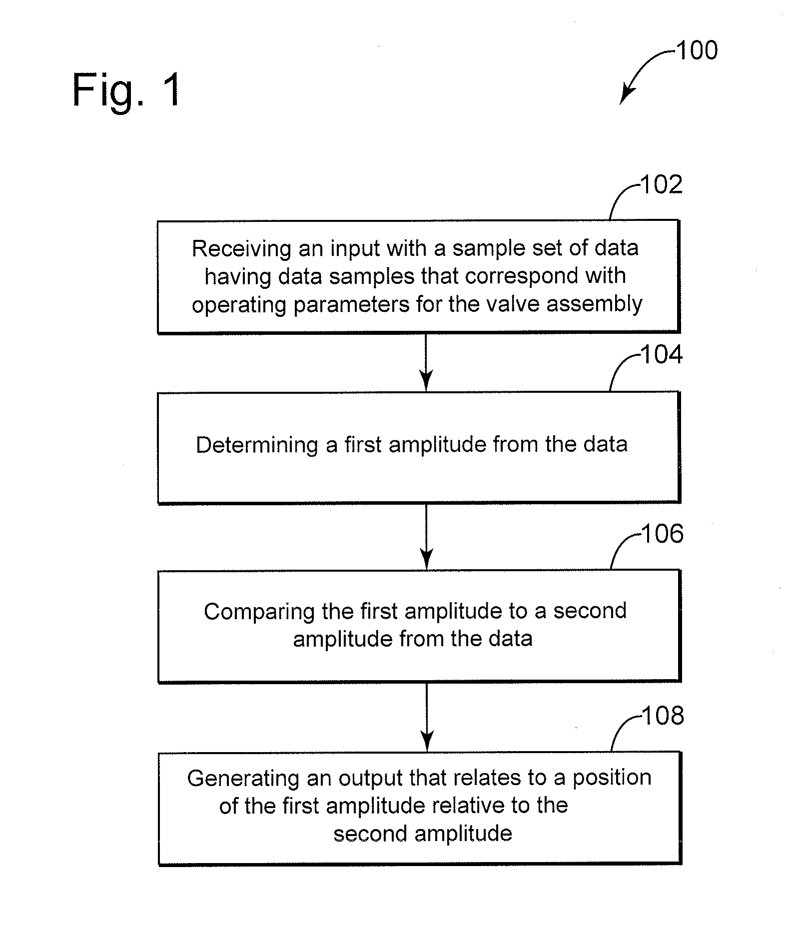
[0019]FIG. 1 depicts a flow diagram of an exemplary embodiment of a method 100 for use on and / or as part of a valve assembly and a process control system. This diagram outlines steps that may embody instructions for one or more computer-implemented methods and / or programs. In FIG. 1, the embodiment includes, at step 102, receiving an input with a sample set of data, the sample set comprising data samples col...


PUM


Abstract

A method for processing operating data (e.g., position, setpoint, and pressure) for a valve assembly. The method is configured to associate characteristics of operation for the valve assembly with a root cause and/or a contributing factor. In one embodiment, the method can assign a first amplitude with a value that quantifies movement or “jump” of the valve stem that results from stick-slip on the valve assembly. The method can also assign a second amplitude with a value that quantifies a change in the data for the setpoint. The method can further ascertain the relationship or “position” of the first amplitude relative to the second amplitude, or vice versa. The method can use the relationship between the first amplitude and the second amplitude to indicate the root cause of the operation of the valve assembly.

Description

CROSS-REFERENCE TO RELATED APPLICATIONS[0001]The application claims the benefit of priority to U.S. Provisional Application Ser. No. 62 / 049,287, filed on Sep. 11, 2014, and entitled “METHOD FOR DETERMINING AMPLITUDE OF STICK-SLIP ON A VALVE ASSEMBLY AND IMPLEMENTATION THEREOF,” the content of which is incorporated by reference herein in its entirety. This application is a continuation-in-part of U.S. patent application Ser. No. 14 / 231,505, filed on Mar. 31, 2014, and entitled “SYSTEM AND METHOD FOR DETECTING STICK-SLIP,” the content of which is incorporated by reference herein in its entirety.BACKGROUND[0002]The subject matter disclosed herein relates to processing of data that corresponds with operating parameters for a valve assembly, with particular discussion about methods that use this data to quantify movement of the valve stem due to stick-slip to distinguish the root cause and / or contributing factor of cycling on the valve assembly.[0003]Process lines may include many variet...

Claims


Application Information

Patent Timeline
IPC IPC(8): F16K37/00G01M99/00
CPCG01M99/008F16K37/0083G05B19/44G05B23/0235G05B2219/25232G05B2219/33326G05B2219/41311G05B2219/41304G05B2219/41154G05B2219/45006
Inventor SCHOONOVER, LARRY GENE
Owner DRESSER LLC
Why Eureka
Try Eureka