Floor support structure of vehicle

a technology for supporting structures and vehicles, applied in vehicle arrangements, roofs, transportation and packaging, etc., can solve the problems of inability to restrain the second frame and the width direction of the first frame of the vehicle, and achieve the effect of not increasing the number of components and being convenient to moun

Active Publication Date: 2015-10-01
HONDA MOTOR CO LTD
View PDF2 Cites 1 Cited by
  • Summary
  • Abstract
  • Description
  • Claims
  • Application Information

AI Technical Summary

Benefits of technology

The present invention provides a floor support structure for vehicles that can easily suppress displacement in different directions. The floor support structure includes a floor that extends in the vehicle width direction and is supported by a floor stay made up of multiple main stays and a sub-stay. The main stays are spaced apart and extend in the vehicle forward and rearward direction, providing load distribution and restraint against displacement. The sub-stay connects the main stays to restrain displacement in the vehicle width direction. By supporting the floor in this way, displacement of each component member in the vehicle can be easily suppressed.

Problems solved by technology

However, displacement in the vehicle width direction of the first frame and the second frame is not able to be restrained by the structure disclosed in the patent reference 1.
However, this incurs complication of manufacturing and assembling and so is undesirable.

Method used


Image

  • Floor support structure of vehicle
  • Floor support structure of vehicle
  • Floor support structure of vehicle

Examples


Embodiment Construction

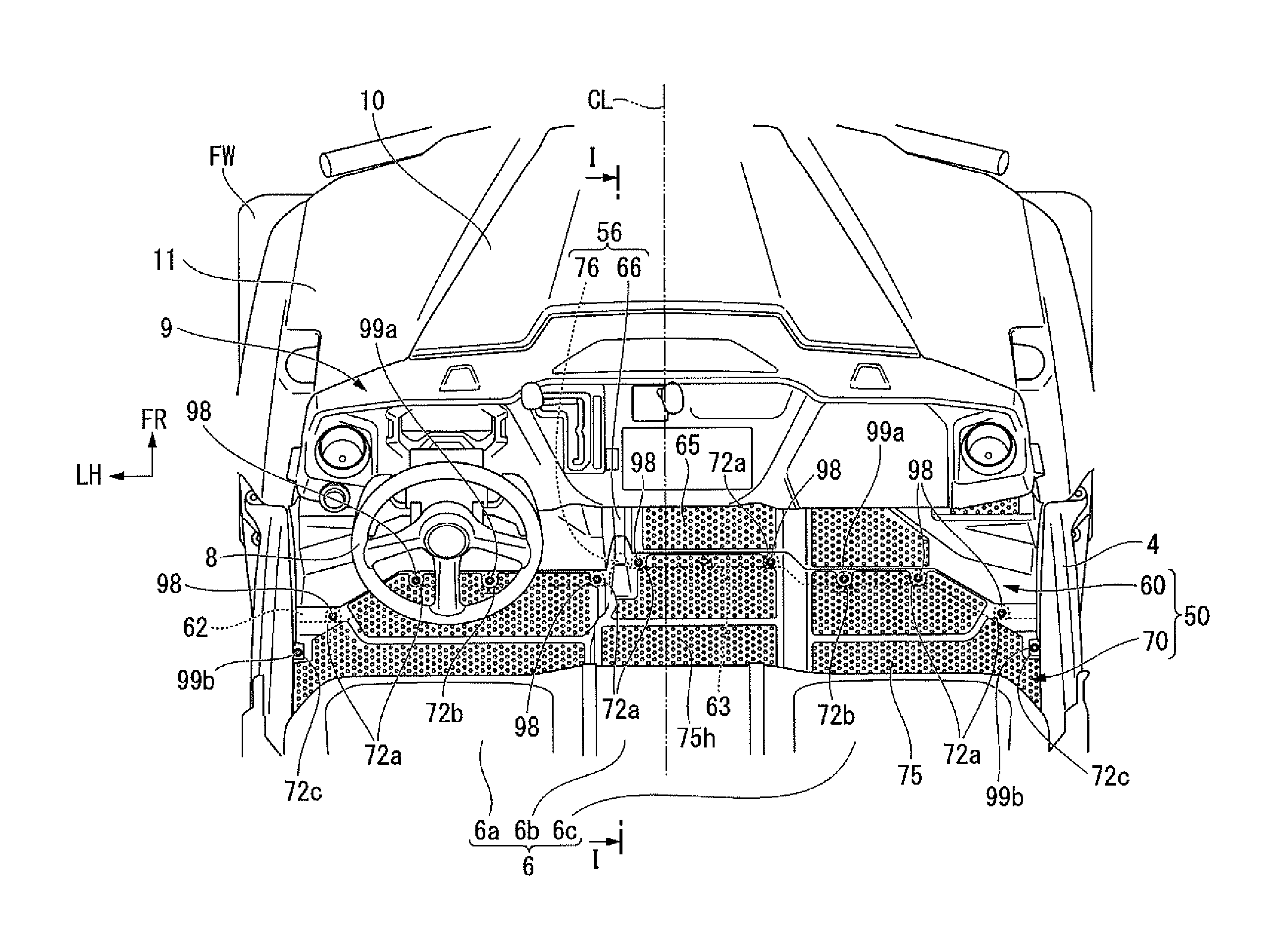
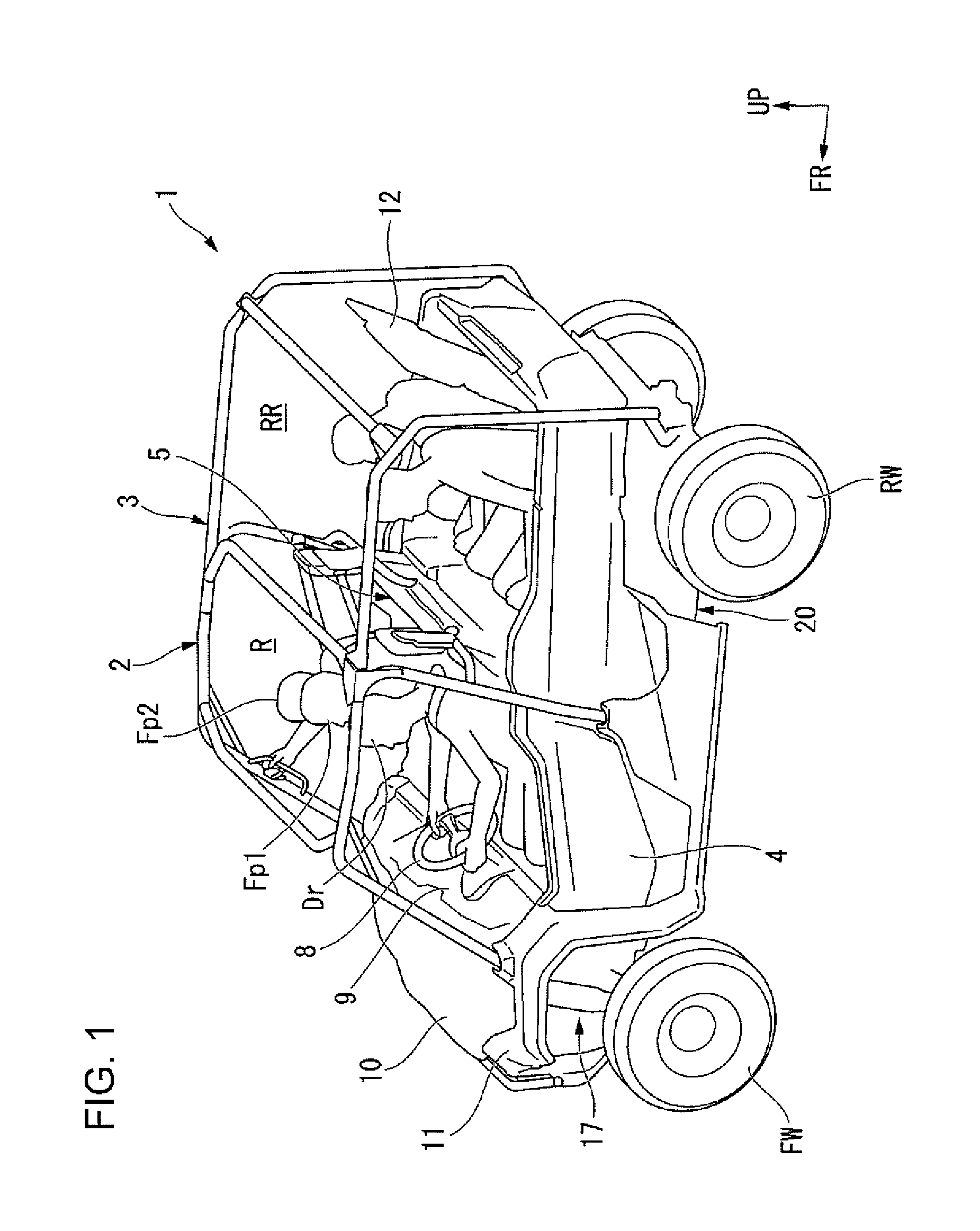
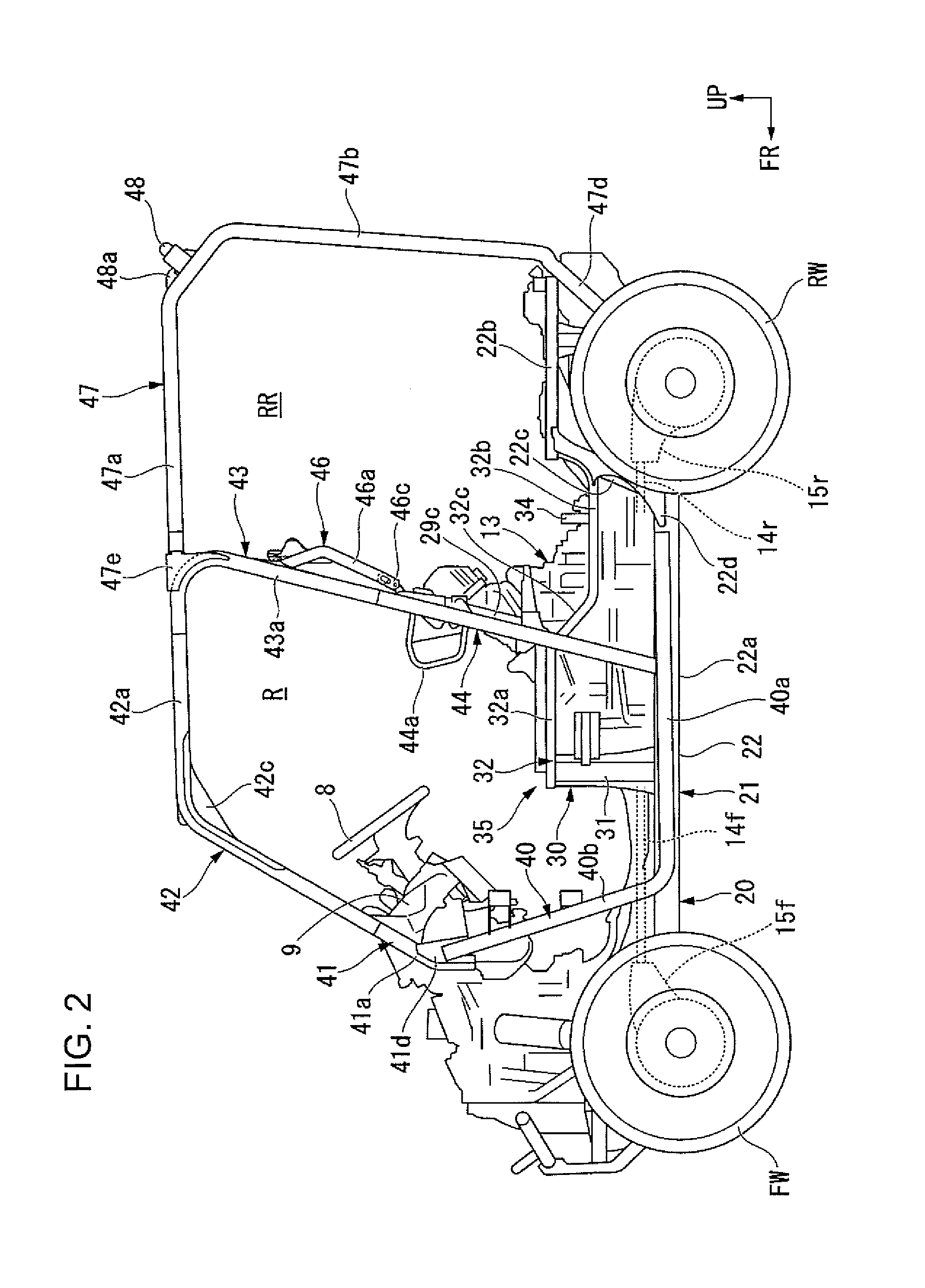
[0031]Hereinafter, embodiments of the present invention will be explained with reference to accompanying drawings.

[0032]In the following description, the orientation such as front, rear, left, right and the like shall be identical to the orientation of a vehicle to be explained hereunder, unless otherwise stipulated. Moreover, at proper places in the drawings to be used in the following explanation, there are designated an arrow FR indicating the forward direction of the vehicle, an arrow LH indicating the left direction of the vehicle and an arrow UP indicating the upward direction of the vehicle. In addition, a line CL in the drawing indicates a center line in the left and right direction of the vehicle.

[0033]According to an embodiment, a four-wheeled vehicle 1 (hereinafter, referred to simply as a “vehicle 1”) shown in FIG. 1 is a side by side type MUV (multi utility vehicle) in which three occupants Dr, Fp1, Fp2 ride side by side in the vehicle width direction in a front seat. T...


PUM


Abstract

A floor support structure of a vehicle comprises a floor extending in the vehicle width direction so as to allow occupants sitting side by side in the vehicle width direction to put their feet thereon. The floor includes a plane surface part and separating a vehicle interior from a vehicle exterior, a body for supporting each of front and rear end portions of the floor in the forward and rearward direction of the vehicle and each of left and right end portions of the floor in the vehicle width direction, and a floor stay making contact with a lower surface in or around the middle in the vehicle width direction of the floor so as to support the floor. The floor stay comprises a plurality of main stays and a sub-stay.

Description

BACKGROUND[0001]1. Field[0002]The present invention relates to a floor support structure of a vehicle.[0003]2. Description of the Related Art[0004]A floor support structure of a vehicle is disclosed in patent reference 1 (Japanese Patent No. 4,132,746), for example. This floor support structure includes a support member extending from a vehicle body frame, a first wire rod frame extending from a distal end portion of the support member to the vehicle body frame, the first frame being suspended from the vehicle body frame by a second wire rod frame, and a foot board covering the first frame and the support member. The foot board covers the first wire rod frame and the support member so as to distribute a load to these members, so that each of component members can be prevented from plastic deformation under a load from the ground and can provide flexibility.[0005]However, displacement in the vehicle width direction of the first frame and the second frame is not able to be restrained ...

Claims


Application Information

Patent Timeline
Patent Type & Authority Applications(United States)
IPC IPC(8): B62D25/20B62D27/02B62D21/09
CPCB62D25/20B62D27/02B62D21/09B62D23/005
Inventor KARUBE, SHINICHIKAMIYAMA, TAKESHITANO, YOSHIHIRO
Owner HONDA MOTOR CO LTD
Why Eureka
Try Eureka