
Vehicle travel controller

a technology of vehicle travel controller and travel control, which is applied in the direction of machines/engines, road transportation, instruments, etc., can solve the problem of restraint of the improvement effect of fuel consumption, and achieve excellent fuel consumption, excellent fuel consumption, and excellent fuel consumption

Active Publication Date: 2015-10-01
TOYOTA JIDOSHA KK
View PDF1 Cites 19 Cited by
  • Summary
  • Abstract
  • Description
  • Claims
  • Application Information

AI Technical Summary

Benefits of technology

The patent describes a running control device for a vehicle that improves fuel consumption by performing two modes of inertia running. The first mode is performed with the engine stopped and the second mode is performed with the engine kept rotating. By stopping the engine and quickly increasing the speed of rotation, the device achieves excellent fuel consumption. On the other hand, by keeping the engine running and increasing the speed of rotation, the device ensures the proper vehicle braking force. The device also adapts to driving situations such as down-slopes and up-slopes to further improve fuel consumption.

Problems solved by technology

If an execution condition is defined in accordance with one of the characteristics regardless of the difference in a characteristic of the brake performance, this leads to a problem that a fuel consumption improvement effect is restrained although the amplification effect on the brake force can be ensured, or that the amplification effect on the brake force is reduced although fuel consumption is improved.

Method used


Image

  • Vehicle travel controller
  • Vehicle travel controller
  • Vehicle travel controller

Examples


example

[0043]An example of the present invention will now be described in detail with reference to the drawings.

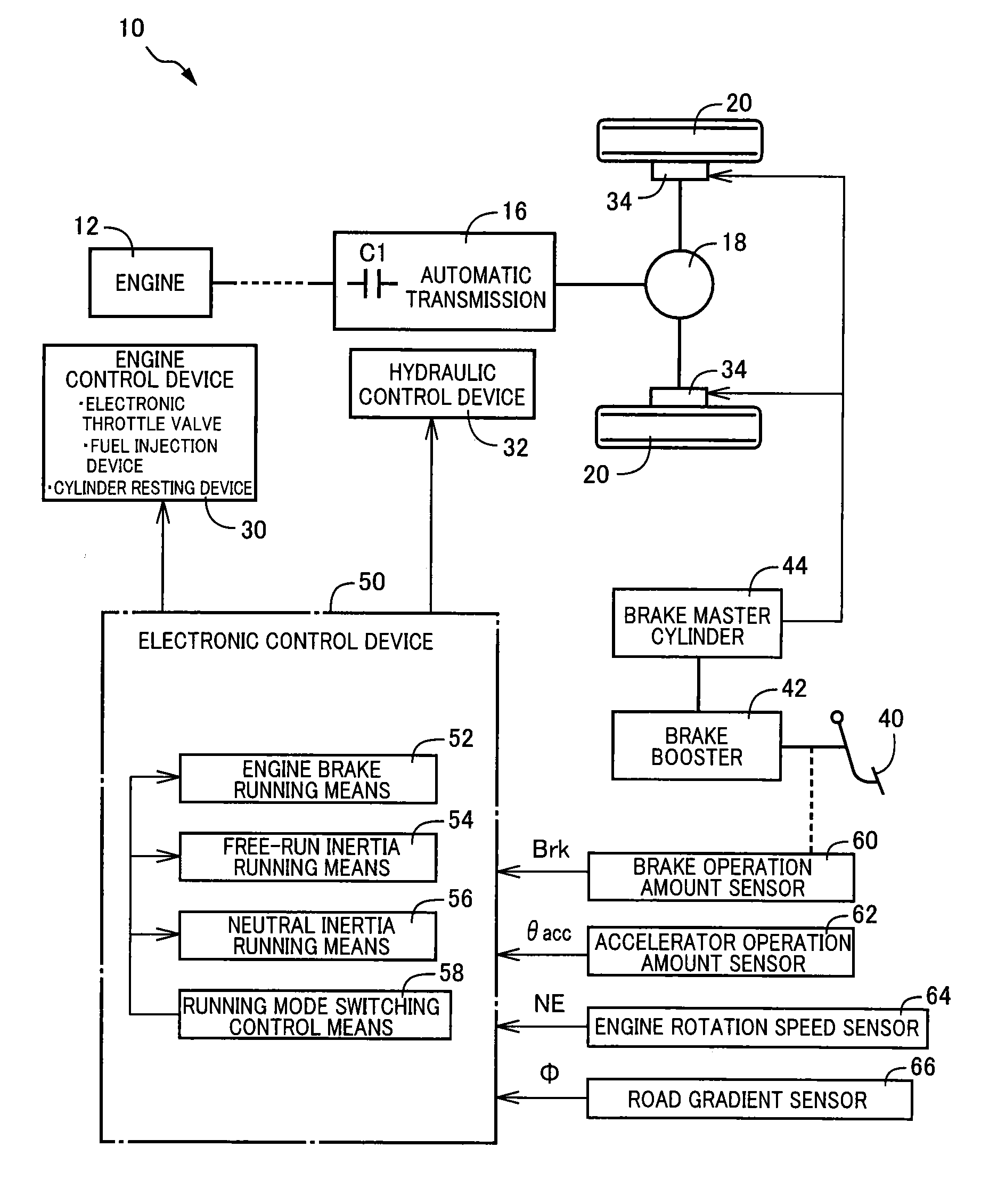
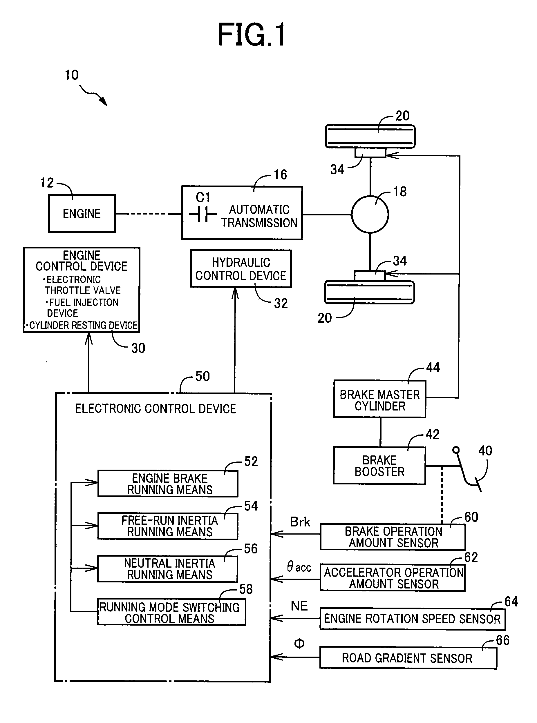
[0044]FIG. 1 is a schematic configuration diagram including a schematic of a vehicle drive device 10 to which the present invention is preferably applied along with a main portion of a control system. The vehicle drive device 10 includes as a drive force source an engine 12 that is an internal combustion engine such as a gasoline engine and a diesel engine generating power from combustion of fuel, and the output of the engine 12 is transmitted from an automatic transmission 16 via a differential gear device 18 to left and right wheels 20. A damper device and a power transmission device such as a torque converter are disposed between the engine 12 and the automatic transmission 16, and a motor generator acting as a drive force source can also be disposed therebetween.

[0045]The engine 12 includes an engine control device 30 having various pieces of equipment necessary for output co...


PUM


Abstract

A running control device of a vehicle including an engine, a brake operation member, and a brake booster, is configured to execute an engine brake running mode performed with the engine coupled to wheels and an inertia running mode performed with an engine brake force made lower than that in the engine brake running mode. The running control device executes first and second inertia running modes. The first inertia running mode is terminated when a brake request amount becomes equal to or greater than a predefined first determination value while the first inertia running mode is performed. The second inertia running mode is terminated and a return to the engine brake running mode is made when the brake request amount becomes equal to or greater than a predefined second determination value larger than the first determination value while the second inertia running mode is performed.

Description

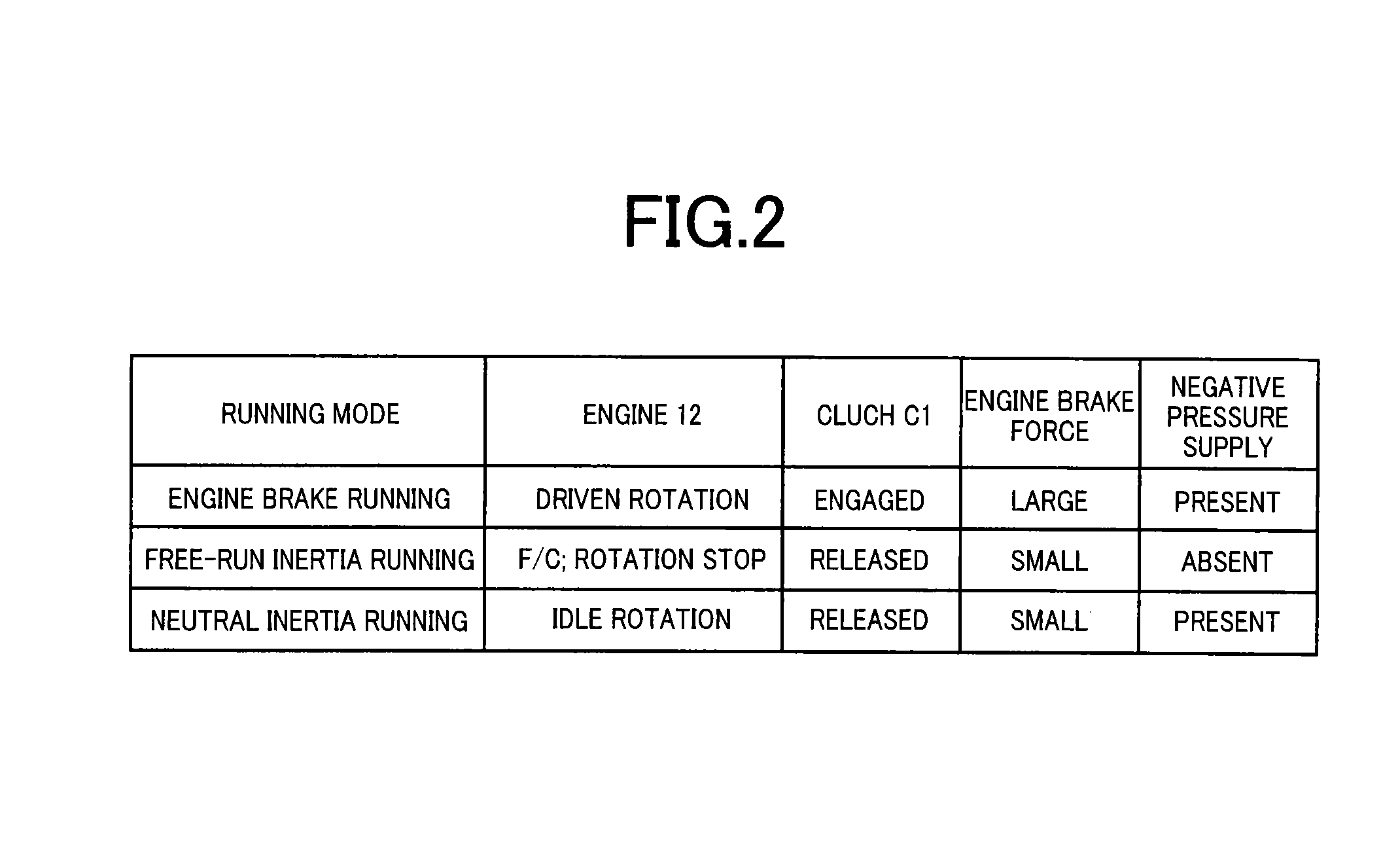
TECHNICAL FIELD[0001]The present invention relates to a running control device of a vehicle and particularly to a technique of further improving fuel consumption while ensuring an amplification effect on a brake force at the time of a brake operation in a vehicle configured to execute an inertia running mode performed with an engine brake force made lower than that of an engine brake running mode.BACKGROUND ART[0002]With regard to an engine brake running mode performed with engine brake applied by driven rotation of an engine while the engine is coupled to wheels, an inertia running mode performed with an engine brake force made lower than that of the engine brake running mode is conceived for extending a running distance and improving fuel consumption. A device described in Patent Document 1 is an example thereof and, two types of control modes are proposed as (a) a first inertia running mode performed with rotation of the engine stopped and (b) a second inertia running mode perfor...

Claims


Application Information

Patent Timeline
Patent Type & Authority Applications(United States)
IPC IPC(8): B60W30/18B60W10/18B60W10/06
CPCB60W30/18136B60W10/06B60W2540/12B60W2510/18B60W2510/069B60W10/18B60W10/02B60W10/184B60W30/18072F02D29/02B60W2030/1809B60W10/188F16H61/21F16D2500/50676F16D48/066F16D2500/1085F16D2500/3067F16D2500/3101F16D2500/3127F16D2500/3165F16D2500/5029F16D2500/5085F16D2500/50858B60W2552/15Y02T10/60
Inventor KUROKI, RENTAROHIRAI, TAKUYAMITSUYASU, MASAKIKIM, JONGGAPMATSUNAGA, MASAKISUZUKI, TAKEAKIKOGURE, TAKAYUKIOKAMURA, YUKARISATO, AKIHIROKINOSHITA, YUSUKEKIDO, YASUNARI
Owner TOYOTA JIDOSHA KK
Learn More