
Systems and Methods for Controlling Fuel Vapor Flow in an Engine-Driven Generator

Active Publication Date: 2015-09-24
ILLINOIS TOOL WORKS INC
View PDF2 Cites 5 Cited by
  • Summary
  • Abstract
  • Description
  • Claims
  • Application Information

AI Technical Summary

Benefits of technology

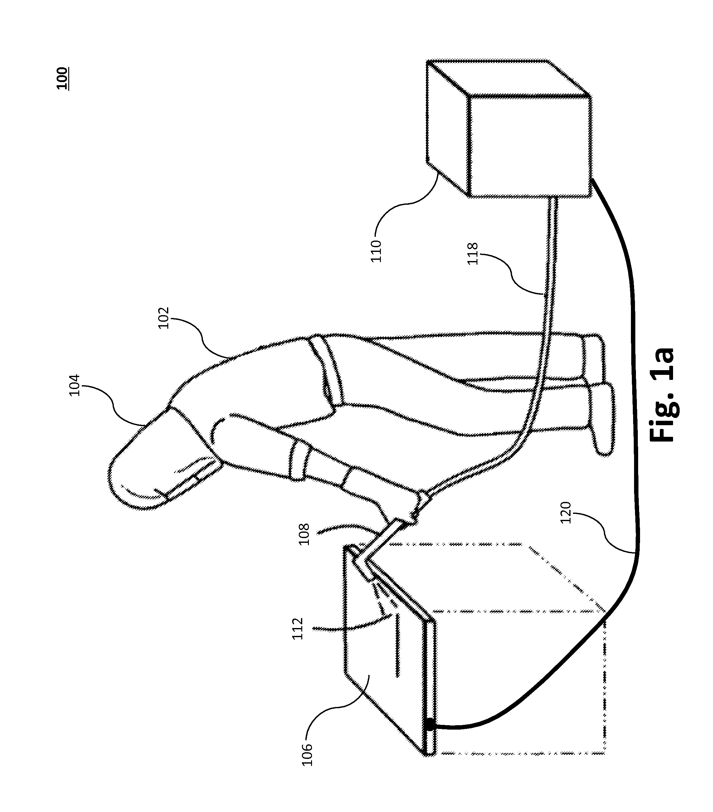
The invention relates to fuel delivery systems for generators, particularly those used in welding equipment. The patent describes a system that includes a fuel tank, a valve, a pressure regulator, and a control device. The valve is positioned between the fuel tank and the engine's air intake passage and can transition between two positions: one that allows fuel vapor to flow and another that inhibits it. The pressure regulator is positioned in line between the fuel tank and the engine and can release fuel vapor when a certain pressure threshold is reached. The control device can transition the valve between the two positions based on measured oil pressure or voltage. The technical effect of this invention is to control the flow of fuel vapor from the fuel tank to the engine's air intake passage, which can improve engine performance and fuel efficiency.

Problems solved by technology

When fuel vapors are present at the combustion air intake of the engine during shutdown of the engine-driven generator, however, the engine-driven generator may “diesel” or “run on.” When this occurs, the engine-driven generator may operate undesirably for a period of time (e.g., multiple seconds or minutes).

Method used


Image

  • Systems and Methods for Controlling Fuel Vapor Flow in an Engine-Driven Generator
  • Systems and Methods for Controlling Fuel Vapor Flow in an Engine-Driven Generator
  • Systems and Methods for Controlling Fuel Vapor Flow in an Engine-Driven Generator

Examples


first embodiment

[0057]FIG. 5b illustrates a block diagram of a vapor control system 500b with pressure regulation for controlling fuel vapor flow and pressure in the engine-driven welding equipment 110 using a three-way valve 410 that directly enables flow from the inlet port 506 to the relief port 510, or from the inlet port 506 to the outlet port 508. The welding equipment 110 may direct fuel vapor to be used for engine 304 combustion while the engine 304, or welding equipment 110, is operating. In certain aspects it is useful to maintain a predetermined pressure in the fuel tank 402 while the engine 304 is operating. To accomplish this, a pressure regulator 526 may be positioned in series between the fuel tank 402 and the three-way valve 410 such that the pressure in the tank 402 may be a positive value. In certain aspects, an orifice may be provided to facilitate pressure regulation.

[0058]This configuration allows the fuel vapors to be directed to the engine 304 when running and solves engine r...

second embodiment

[0063]FIG. 5c illustrates a block diagram of a vapor control system 500c with pressure regulation for controlling fuel vapor flow and pressure in the engine-driven welding equipment 110 using a three-way valve 410 that directly enables flow from the inlet port 506 to the relief port 510, or from the inlet port 506 to the outlet port 508. As illustrated, the valve 410 includes a default position 514 and a controlled position 516. In certain aspects, pressure regulation may be performed on the output of the three-way valve 410 in the port leading to the engine 304. Thus, as illustrated, in lieu of positioning the pressure regulator 526 between the fuel tank 402 and the three-way valve 410 (as illustrated in FIG. 5b), the pressure regulator 526 may be positioned between the three-way valve 410 and the engine 304.

[0064]The pressure regulator 526 may be configured to release fuel vapor between the valve 410 and the fuel tank 402 (or the valve 410 and the air intake passage of the engine ...


PUM


Abstract

A portable engine-driven system comprising an engine having an air intake passage, a fuel tank operatively coupled to the engine, a valve, and a pressure regulator. The valve may be coupled between the fuel tank and the air intake passage and configured to transition between a first position and a second position. The first position may allow fuel vapor to flow between the fuel tank and the air intake passage and the second position may inhibit the fuel vapor from flowing between the fuel tank and the air intake passage. The pressure regulator may be positioned in line between the fuel tank and the air intake passage.

Description

RELATED APPLICATIONS[0001]This application claims priority to, and is a continuation-in-part of co-pending U.S. application Ser. No. 13 / 423,980, having a filing date of Mar. 19, 2012, (U.S. Publication No. 2012 / 0240900), which is incorporated herein by reference, and which claims priority to U.S. Provisional Application No. 61 / 466,317, having a filing date of Mar. 22, 2011, which is also incorporated herein by reference in its entirety.BACKGROUND OF THE INVENTION[0002]Welding is a process that has increasingly become ubiquitous in all industries. Welding is, at its core, simply a way of bonding two pieces of metal. Larger welding systems can generate a welding current output in excess of 100 amps, while micro-welding may employ a micro arc under a few amps.[0003]Welding systems may be coupled to the power grid, or use a fuel-powered engine to drive an electric generator, which in turn generates the required current for the specific welding operation. The size of the engine and elect...

Claims


Application Information

Patent Timeline
IPC IPC(8): F02M25/08F02B63/04
CPCF02B63/04F02M25/0836B60K2015/03566B60K15/03504B60K15/03519F02M25/0872F02M25/089F02M35/10222F02D41/004H02K7/1815
Inventor JOCHMAN, NATHAN JOE
Owner ILLINOIS TOOL WORKS INC
Learn More