
Call-giving system of an elevator and method for giving elevator calls in the call-giving system of an elevator

a technology of elevator call and elevator call, which is applied in the direction of elevators, transportation and packaging, etc., can solve the problems of increasing the installation cost of elevators, generating technical servicing work, and not being able to choose the floor in real tim

Inactive Publication Date: 2015-09-24
KONE CORP
View PDF17 Cites 10 Cited by
  • Summary
  • Abstract
  • Description
  • Claims
  • Application Information

AI Technical Summary

Benefits of technology

This patent is about a system for elevators that uses sensors to detect objects or shapes near the elevator and determine what they are. This system can replace the need for call-giving buttons and panels, reducing the need for electrical installations and the need for cleaning. Additionally, the use of virtual target areas can prevent dirt and debris from accumulating on the sensors. Overall, this technology improves safety and efficiency in elevators.

Problems solved by technology

The actual choice of floor is not possible in this case for the user to implement until after stepping into the elevator car.
This increases the costs of elevator installations.
In addition, call-giving buttons and a destination operating panel typically generate technical servicing work and require e.g. regularly wiping clean for reasons of hygiene and tidiness.

Method used


Image

  • Call-giving system of an elevator and method for giving elevator calls in the call-giving system of an elevator
  • Call-giving system of an elevator and method for giving elevator calls in the call-giving system of an elevator

Examples


embodiment 1

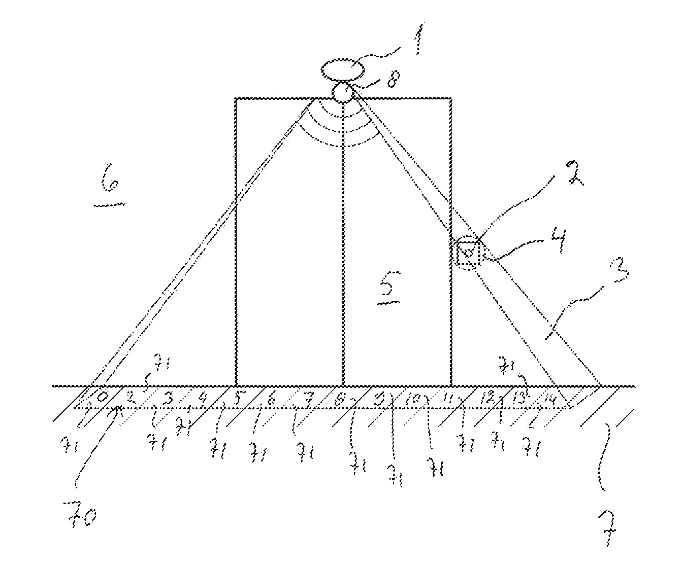
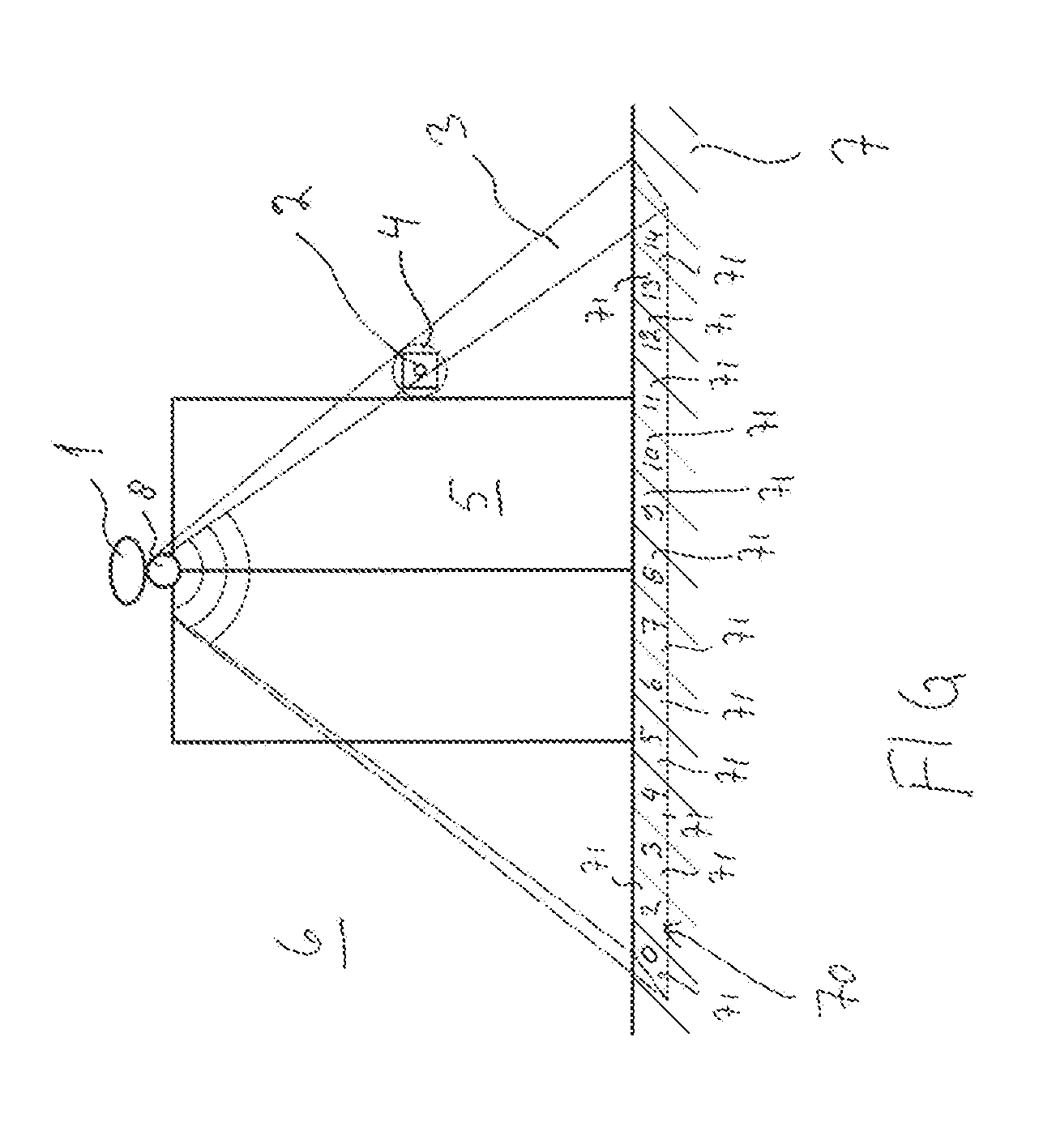
[0023]A laser radar 1 is integrated into the elevator, primarily for the curtain-of-light function for increasing safety. The laser radar 1 covers the defined area 3. The landing call button generally used in elevators is replaced with a stick 2 or with some other identifier, which tells where the landing call-giving device is. When a hand, stick or foot is brought into the area 4 defined for the laser radar 1, a landing call of the elevator is generated by the action of an input transmitted by the laser radar 1.

embodiment 2

[0024]A landing call is generated when a user steps into a certain defined part 70 in an elevator lobby 6, said part being in an area 3 covered by the laser radar 1.

[0025]In addition to this, or alternatively, if own points or boxes 71 are defined for each of the respective various floor calls (for each floor 0, 2, 3, 4, 5, 6, 7, 8, 9, 10, 11, 12, 13, 14 of the building reachable with an elevator, an own separate box 71 is selected), instead of, or in addition to, a landing call also a floor call to defined floors can be automatically generated, so long as it is sufficiently clearly indicated to a user in which point or box 71 of the lobby or waiting landing a call to which floor will be generated.

[0026]Indication is preferably implemented with a marking made on the floor 7. In addition to this, or alternatively, the marking can be reflected or projected onto the floor.

embodiment 3

[0027]Use of a call-giving device, e.g. a call button assembly or destination operating panel, e.g. in the case of a visually impaired user: the user takes his / her hand, stick or foot into the defined point or area 4, 70, 71 in connection with the operating area of the call-giving device and laser radar 1. The user is guided e.g. with voice control in such a way that the voice control states the floor numbers in sequence and when the floor wanted by the user is said, he / she pulls his / her hand, stick or foot away from the point or area 4, 70, 71 defined for the laser radar 1, which locks the selected floor and a call is generated. The acoustic signal needed for voice control is reproduced preferably via a loudspeaker 8.


PUM


Abstract

The call-giving system of an elevator comprises at least one optical sensor and / or a microwave sensor, which is / are configured to give a signal to the call system of the elevator about an object or shape coming into one or more virtual target areas defined in the detection area. The patent application also comprises an independent claim for a method for giving elevator calls in the call-giving system of an elevator.

Description

[0001]This application is a continuation of PCT International Application No. PCT / FI2014 / 050012 which has an International filing date of Jan. 8, 2014, and which claims priority to Finnish patent application number 20135023 filed Jan. 8, 2013, the entire contents of both of which are incorporated herein by reference.FIELD OF THE INVENTION[0002]The invention relates to call-giving systems of elevators.TECHNICAL BACKGROUND[0003]Elevator calls are generally given by pressing call-giving buttons. Often in a lobby or on a floor level there is a button or buttons with which an elevator call is given. By pressing one button, a call “elevator come here” is given. By pressing one of two buttons a call “user wants to go up” or “user wants to go down” is given. The actual choice of floor is not possible in this case for the user to implement until after stepping into the elevator car.[0004]In new elevators, primarily in those intended for high-rise buildings, a destination operating panel (DOP...

Claims


Application Information

Patent Timeline
Patent Type & Authority Applications(United States)
IPC IPC(8): B66B1/34B66B1/46
CPCB66B1/468B66B1/3492B66B1/46B66B2201/00B66B1/467B66B2201/4615B66B2201/4623B66B2201/4638B66B1/2408
Inventor SALMIKUUKKA, JUKKA
Owner KONE CORP
Learn More