
Medical applicator and methods of making

a technology of medical devices and applicators, applied in the field of medical devices, can solve the problems of affecting the amount of radiation delivered to the target tissue, the applicator may be more likely to shift, and the treatment is delivered to the wrong area or dispersed,

Active Publication Date: 2015-09-24
NUCLETRON OPERATIONS
View PDF3 Cites 3 Cited by
  • Summary
  • Abstract
  • Description
  • Claims
  • Application Information

AI Technical Summary

Benefits of technology

The present patent is about a method of making a medical applicator for delivering treatment to a patient. The method involves using a three-dimensional image of the patient's anatomical cavity, which contains an expandable container, to create a design template for the applicator. The applicator is then formed based on this template, using a three-dimensional printer, to deliver the treatment to the patient. The method can be used to create applicators for brachytherapy treatment or other medical purposes. The technical effect of this patent is to provide a more precise and customizable method for creating medical applicators for delivering treatment to patients.

Problems solved by technology

Movement or misalignment of the applicator may affect the amount of radiation delivered to the target tissue.
Misalignment could cause delivery of treatment to the wrong area or dissipation of treatment before contacting the target area.
If the applicator does not fit the contours of the patient's anatomy, the applicator may be more likely to shift.
Even if it stays in place, the applicator may not be able to contact optimal portions of the target tissue.
While applicators may be available in different sizes, variations in patient anatomy, tumor location, tumor growth, and disease state may hinder the ability of even an appropriately sized applicator from delivering an optimal dosage of treatment.
Further, a limited selection of applicator types and configurations may confine the number treatment regimens available to a clinician.

Method used


Image

  • Medical applicator and methods of making
  • Medical applicator and methods of making
  • Medical applicator and methods of making

Examples


Embodiment Construction

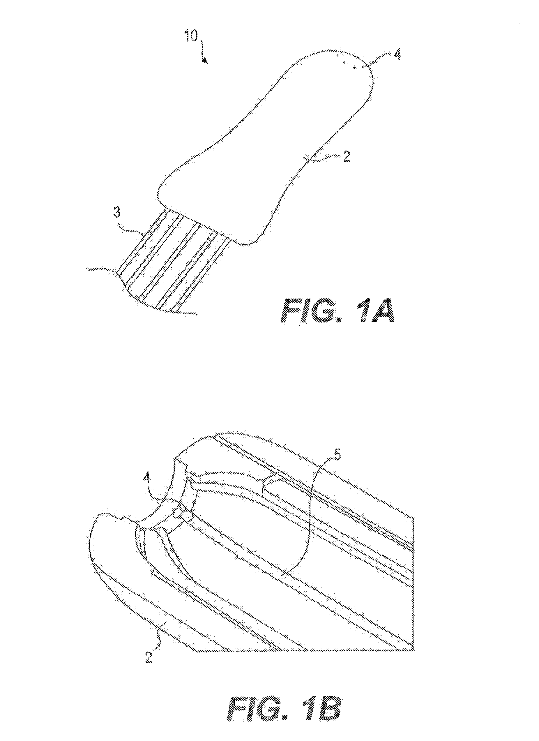
[0021]Reference will now be made in detail to the exemplary embodiments of the present disclosure described below and illustrated in the accompanying drawings. Wherever possible, the same reference numbers will be used throughout the drawings to refer to same or like parts. For purposes of this disclosure, “proximal” refers to an end closer to the clinician during use, and “distal” refers to an end further from the clinician during use.

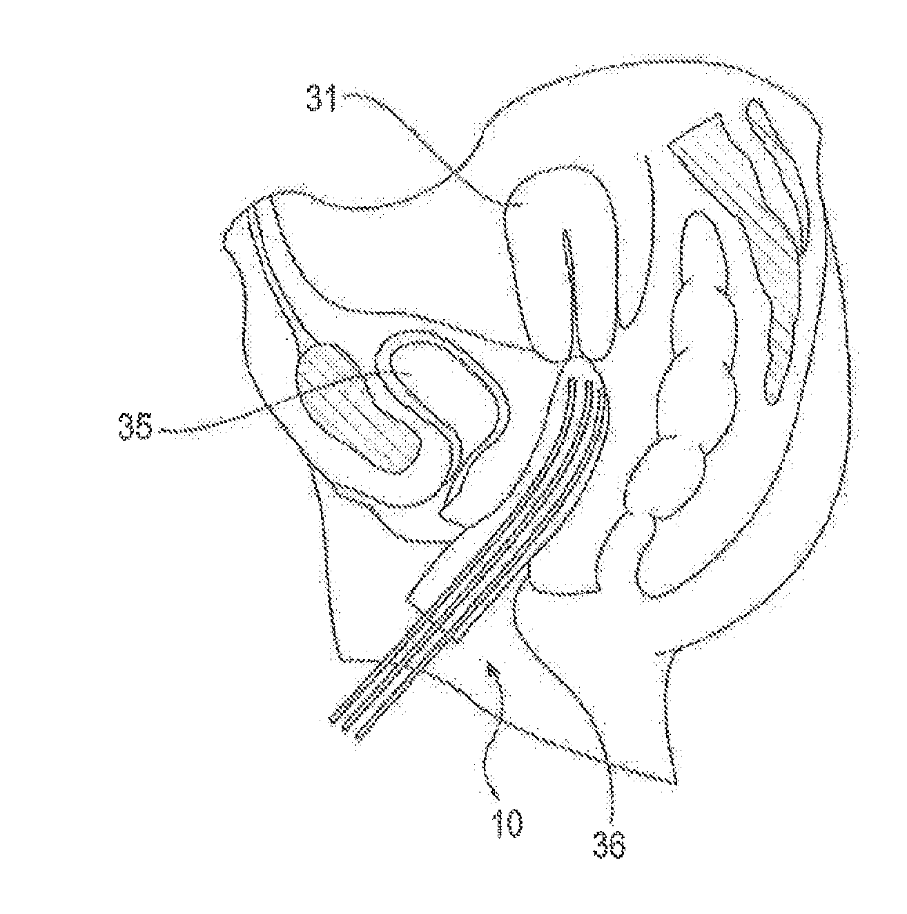
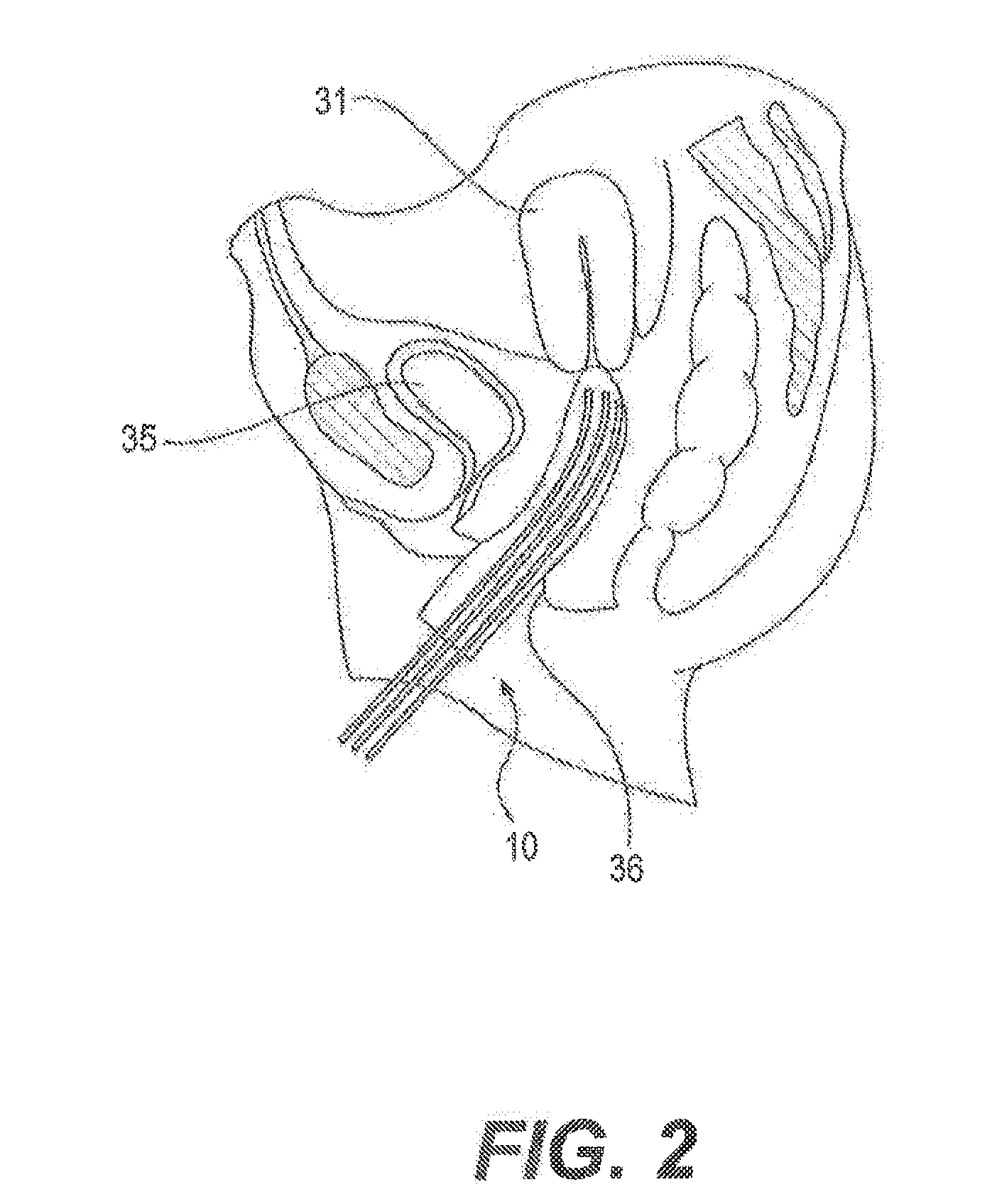
[0022]While the present disclosure is described herein with reference to illustrative embodiments for particular applications, such as brachytherapy applicators for gynecological use, it should be understood that the embodiments described herein are not limited thereto. Those having ordinary skill in the art and access to the teachings provided herein will recognize additional modifications, applications, embodiments, and substitution of equivalents that all fall within the scope of the invention. For example, the principles described herein may be us...


PUM

PropertyMeasurementUnit
Pressureaaaaaaaaaa
Shapeaaaaaaaaaa

Abstract

Embodiments of the present disclosure are directed to forming an applicator for insertion into an anatomical cavity of a patient for delivering a treatment to the patient The method may include receiving a three-dimensional image of the anatomical cavity, wherein the three-dimensional image is generated while the anatomical cavity contains an expandable container adjacent a tissue region of the patient The container may be expanded when contained in the anatomical cavity to substantially conform to the shape of at least a portion of the tissue region forming at least a portion of the anatomical cavity. The method may further include isolating, from the three-dimensional image, a first sub-image corresponding to an image of the filled expanded container and using the sub-image as a design template for forming the applicator for use with the patient.

Description

FIELD OF THE INVENTION [0001]Embodiments of the present disclosure relate to applicators, and more particularly, to brachytherapy applicators for positioning one or more catheters or needles at a predetermined area of tissue.BACKGROUND OF THE INVENTION[0002]Brachytherapy is a method of treating cancer by placing radioactive sources either into or next to an area of tissue requiring treatment. Delivering radiation directly to the target treatment area may allow a clinician to administer higher doses of radiation while decreasing the impact on surrounding, healthy tissue.[0003]During treatment, a brachytherapy applicator may be positioned adjacent the target treatment area. The applicator may be used to align catheters and / or needles with the treatment area and position them for the delivery of radioactive sources to the target tissue. Catheters incorporated in the applicator may be connected to a source of treatment, for example, an afterloader, and forms of treatment, such as radioa...

Claims


Application Information

Patent Timeline
IPC IPC(8): A61N5/10B29C67/00A61B19/00
CPCA61N5/1016A61B19/50B29C67/0051B29L2031/7546B33Y10/00B33Y80/00A61B2019/502A61B2034/102A61B34/10F04C2270/041A61N2005/1018B29C64/106B29C64/112B29C64/386B29C33/3878B29C33/3842B29C33/3857
Inventor KRECHTING, PAULUS CORNELIS HENDRIKUS MARIA
Owner NUCLETRON OPERATIONS
Learn More