
Gas sensor element, its manufacturing method and gas sensor including the gas sensor element

a technology of gas sensor element and manufacturing method, which is applied in the field of gas sensor element, can solve the problems of increasing lowering the changing the grain-boundary capacitance, so as to achieve high accuracy of the temperature control of the heater, secure high durability of the reference electrode, and suppress the change of the impedance of the gas sensor element.

Active Publication Date: 2015-09-10
DENSO CORP
View PDF0 Cites 11 Cited by
  • Summary
  • Abstract
  • Description
  • Claims
  • Application Information

AI Technical Summary

Benefits of technology

The invention relates to a gas sensor element with improved durability and stability. By using a thicker reference electrode detection portion and a smaller-thickness region for the lead and terminal portions, the cohesion of the reference electrode particles is prevented and the temperature control of the heater is secured with high accuracy. Additionally, the small-thickness region reduces the amount of platinum needed and improves the stability of the gas sensor output. The manufacturing process is simple and reliable.

Problems solved by technology

However, in the above case, in long-term use of the gas sensor, the measurement and reference electrodes will be repeatedly heated by the heater, causing cohesion of platinum particles that constitute the electrodes and thereby changing the grain-boundary capacitance.
Consequently, the complex impedance of the gas sensor element will be increased, thereby lowering accuracy of the temperature control of the heater.
Therefore, even if the formation range of the measurement electrode is set as disclosed in the above patent document, it may be difficult to reliably improve the durability of the measurement electrode.
In addition, for the same reasons as the measurement electrode, it may also be difficult to reliably improve the durability of the reference electrode even if the formation range of the reference electrode is set as disclosed in the above patent document.
Consequently, upon exposure of a detection portion of the reference electrode to high temperature for a long period of time, cohesion of platinum particles may occur at the detection portion, thereby increasing the complex impedance of the gas sensor element.
As a result, it may be impossible to stably and accurately sense the concentration of the specific component in the measurement gas.
However, by setting the large-thickness region to include at least part of the detection portion of the reference electrode, it will become difficult for cohesion of platinum particles constituting the reference electrode to occur with long-term use of the gas sensor element.

Method used


Image

  • Gas sensor element, its manufacturing method and gas sensor including the gas sensor element
  • Gas sensor element, its manufacturing method and gas sensor including the gas sensor element
  • Gas sensor element, its manufacturing method and gas sensor including the gas sensor element

Examples


first embodiment

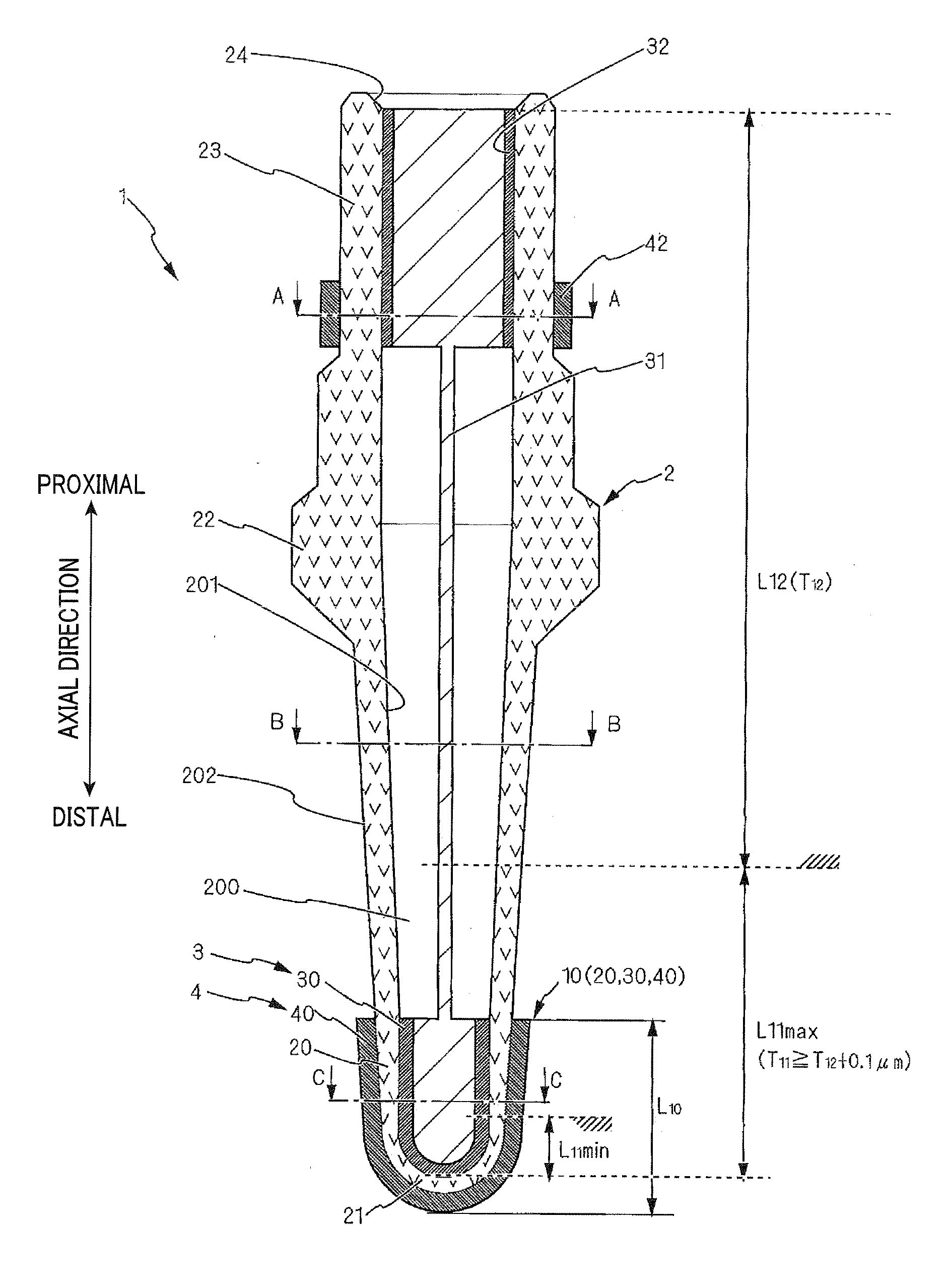
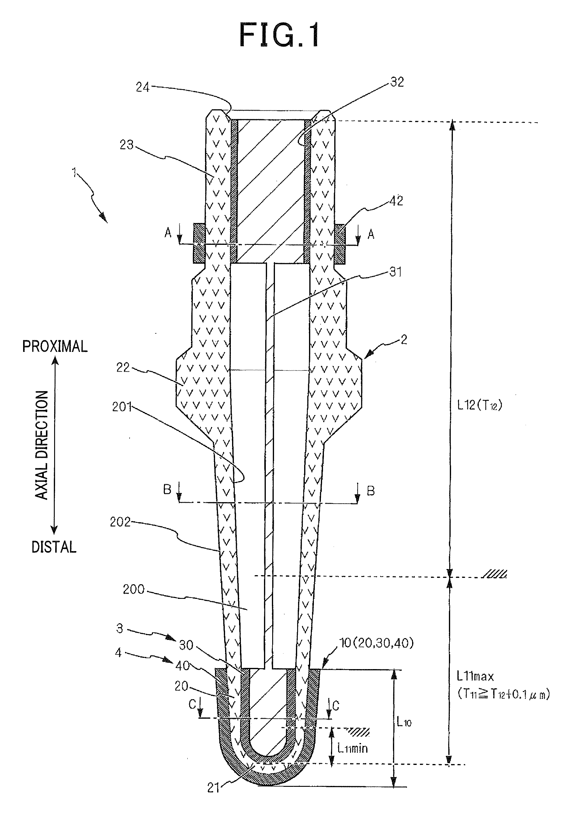
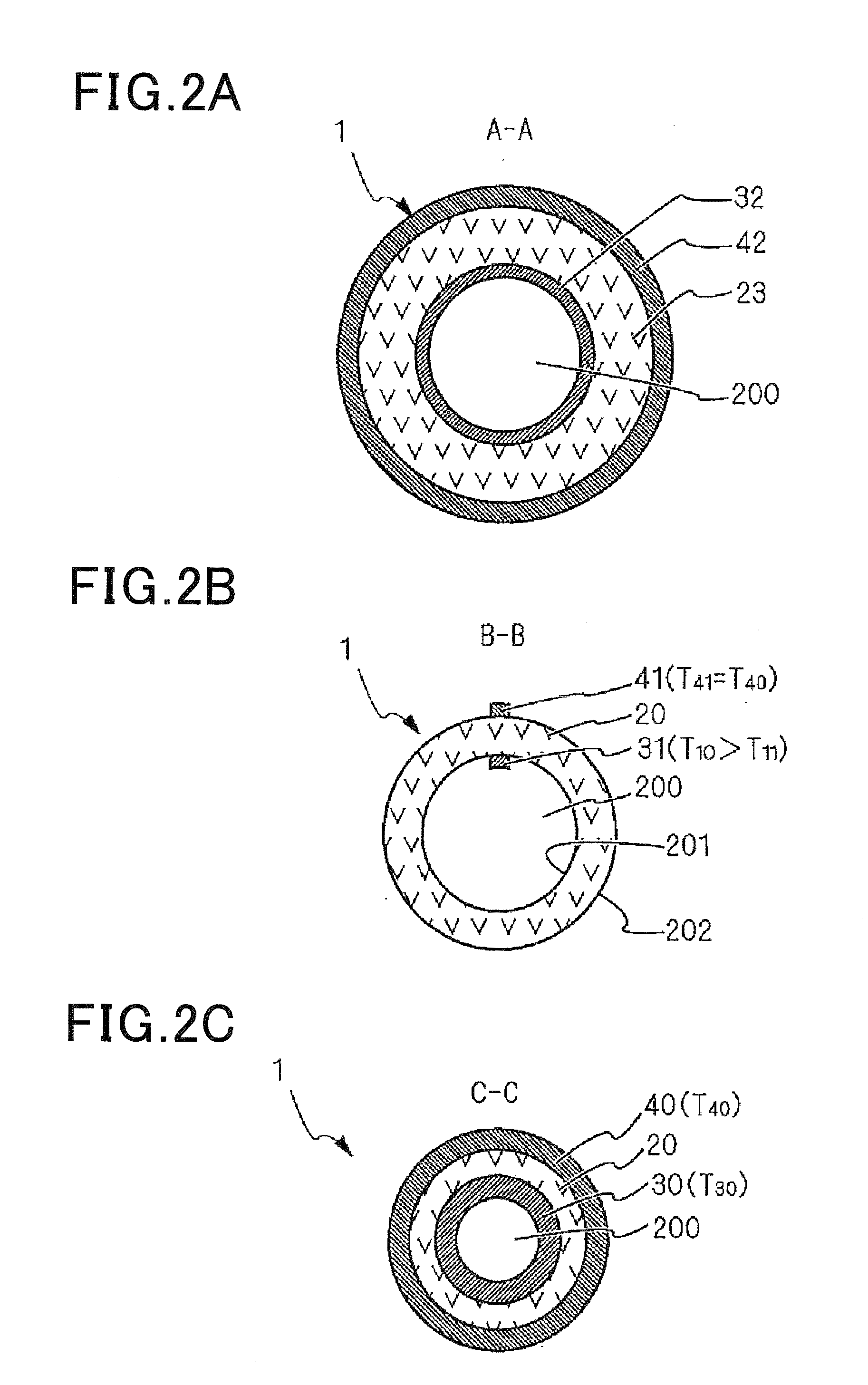
[0059]Referring first to FIGS. 1 and 2A-2D, a gas sensor element 1 will be described.

[0060]The gas sensor element 1 includes a solid electrolyte body 2 having a cup shape (or bottomed tubular shape), a reference electrode 3 formed on an inner surface 201 of the solid electrolyte body 2, and a measurement electrode 4 formed on an outer surface 202 of the solid electrolyte body 2.

[0061]The solid electrolyte body 2 is made, for example, of partially-stabilized zirconia that has oxygen ion conductivity. The solid electrolyte body 2 is formed into the cup shape by a well-known manufacturing method, such as hot pressing.

[0062]In addition, it should be appreciated that the solid electrolyte body 2 may also be formed of other solid electrolyte materials, such as a solid electrolyte material having hydrogen ion conductivity.

[0063]The solid electrolyte body 2 includes a tubular base portion 20 that opens at a proximal end of the solid electrolyte body 2 and a bottom portion 21 that is closed...

second embodiment

[0217]Referring now to FIG. 14, a gas sensor element la will be described.

[0218]The gas sensor element 1a according to the second embodiment has almost the same structure as the gas sensor element 1 according to the first embodiment. Accordingly, only the differences therebetween will be described hereinafter.

[0219]In the first embodiment, the detection portion 30 of the reference electrode 3 is formed on the inner surface 201 of the solid electrolyte body 2 so as to extend from the distal end of the inner surface 201 proximalward. The detection portion 40 of the measurement electrode 4 is formed on the outer surface 202 of the solid electrolyte body 2 so as to extend from the distal end of the outer surface 202 proximalward. Consequently, the inner and outer surfaces of the bottom portion 21 of the solid electrolyte body 2 are respectively covered by the detection portion 30 of the reference electrode 3 and the detection portion 40 of the measurement electrode 4 (see FIG. 1).

[0220...


PUM


Abstract

A gas sensor element includes a cup-shaped solid electrolyte body having closed and open ends, a reference electrode provided on an inner surface of the solid electrolyte body, and a measurement electrode provided on an outer surface of the solid electrolyte body. The reference electrode has a detection portion located closer to the closed end than to the open end of the solid electrolyte body, a terminal portion located closer to the open end than to the closed end of the solid electrode body, and a lead portion connecting the detection and terminal portions. Moreover, the reference electrode has a first thickness in a large-thickness region and a second thickness smaller than the first thickness in a small-thickness region. The large-thickness region includes at least part of the detection portion of the reference electrode, and the small-thickness region includes at least the lead and terminal portions of the reference electrode.

Description

CROSS-REFERENCE TO RELATED APPLICATION[0001]This application is based on and claims priority from Japanese Patent Application No. 2014-41565, filed on Mar. 4, 2014, the content of which is hereby incorporated by reference in its entirety into this application.BACKGROUND[0002]1. Technical Field[0003]The present invention relates to a gas sensor element for sensing the concentration of a specific component in a gas to be measured (to be simply referred to as a measurement gas hereinafter), to a method of manufacturing the gas sensor element, and to a gas sensor which includes the gas sensor element.[0004]2. Description of Related Art[0005]Conventionally, in the exhaust system of an internal combustion engine of a motor vehicle, there is generally arranged a gas sensor for sensing the concentration of a specific component (e.g., oxygen) in the exhaust gas from the engine. Further, based on the concentration of the specific component sensed by the gas sensor, various controls are perfor...

Claims


Application Information

Patent Timeline
IPC IPC(8): G01N27/407
CPCG01N27/4077G01N27/4076G01N27/4071G01N27/4075
Inventor SATOU, MOTOAKI
Owner DENSO CORP
Learn More