Method and apparatus for determining a contrast agent enhancement
a technology of contrast agent and enhancement, applied in the field of methods and apparatus for determining contrast agent enhancement, can solve problems such as temporal resolution in image acquisition
- Summary
- Abstract
- Description
- Claims
- Application Information
AI Technical Summary
Benefits of technology
Problems solved by technology
Method used
Image

Examples
first embodiment
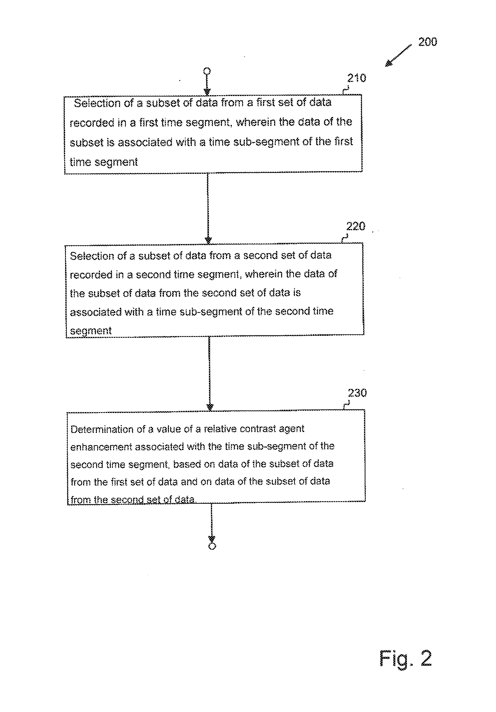
[0141]FIG. 2 shows an example of method 200 according to a
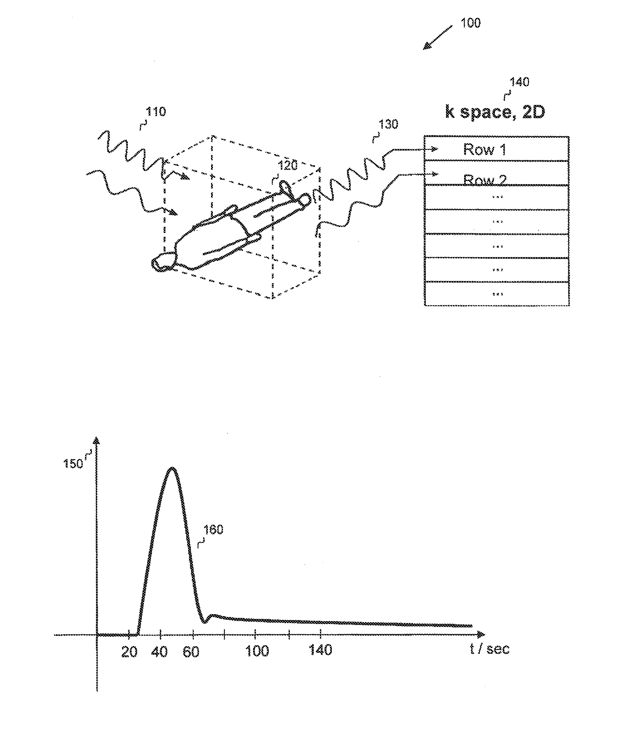
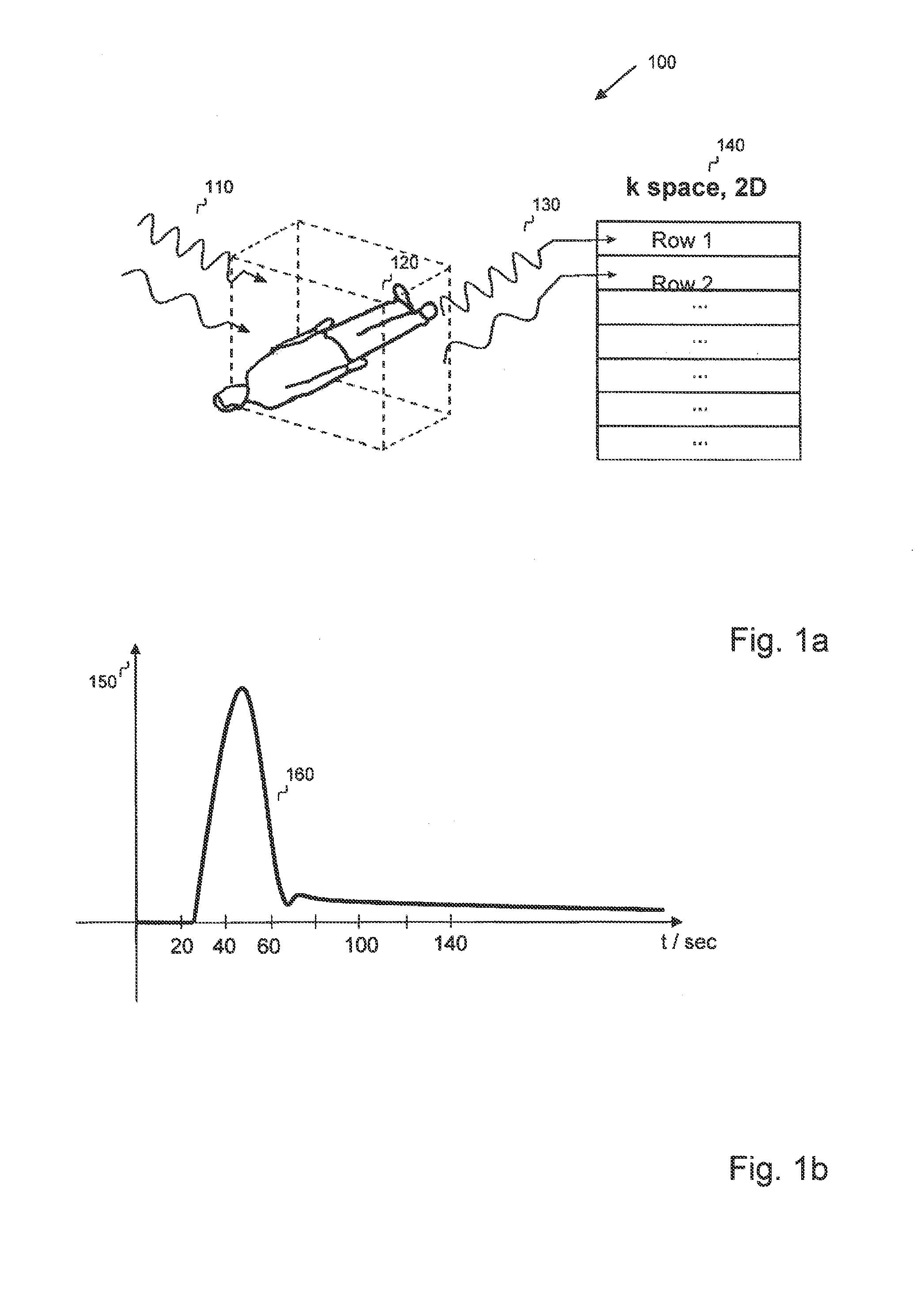
[0142]Method 200 includes in a step 210 the selecting of a subset of data from a first set of data, wherein the first set of data comprises data of a multi-dimensional k space of a magnetic resonance scan recorded without the influence of a contrast agent, which was recorded in a first time segment.
[0143]The multi-dimensional k space can be, for example, a two-dimensional k space corresponding to a two-dimensional MRI scan, wherein the set of data describes a two-dimensional image, or the multi-dimensional k space can also be, for example, a three-dimensional k space corresponding to a three-dimensional MRI scan, wherein the set of data describes a three-dimensional image and thus is able to represent a volume image set of data. The first set of data can be a raw set of data from an MRI scan.
[0144]The multi-dimensional k space can, for example, be frequency-encoded with a plurality of frequencies in a first dimension, wherein...
third embodiment
[0185]FIG. 3 shows an example of method 300 according to a
[0186]This method 300 can be used, for example, to determine a value of a relative contrast agent enhancement associated with the time sub-segment of the second time segment based on data of the subset of data from the first set of data and data of the subset of data from the second set of data in step 230 of method 200 according to the first embodiment.
[0187]To determine the value of a relative contrast agent enhancement associated with the second time sub-segment, method 300 uses in step 230 the calculation of a metric based on the determined differential values, wherein the metric represents a measure for the deviation between the differential values and a value of a relative contrast agent enhancement. These differential values represent, for example, the previously described differential values between data of the subset of the second set of data U2α and data of the subset of the first set of data U1α.
[0188]In step 310, ...
fifth embodiment
[0223]FIG. 6a shows an example of a method 600 ;
[0224]This method 600 can be used, for example, for selecting a subset of data from the first set of data according to step 210 from the method 200 shown in FIG. 2 and for selecting a subset of data from the second set of data according to step 220 and for determining a value of a relative contrast agent enhancement associated with the time sub-segment of the second time segment according to step 230.
[0225]The exemplary method 600 is based, for example, on the assumption that the recording of a set of data Unα in the k space can take place such that the recording starts with a phase step from the plurality of phase steps of one dimension of the at least one additional dimension, wherein, for example in the 3D case, this phase step can be a phase step of a pair of phase steps of the first additional and the second additional dimension, and that the data in the k space associated with the individual frequencies of the plurality of freque...
PUM
 Abstract
Description
Claims
Application Information
 - R&D
- Intellectual Property
- Life Sciences
- Materials
- Tech Scout
- Unparalleled Data Quality
- Higher Quality Content
- 60% Fewer Hallucinations
Browse by: Latest US Patents, China's latest patents, Technical Efficacy Thesaurus, Application Domain, Technology Topic, Popular Technical Reports.
© 2025 PatSnap. All rights reserved.Legal|Privacy policy|Modern Slavery Act Transparency Statement|Sitemap|About US| Contact US: help@patsnap.com