
System and Method for Producing Tubular Concrete Products

a technology of tubular concrete and production system, which is applied in the direction of auxillary shaping apparatus, manufacturing tools, coatings, etc., can solve the problems of complex refitting process, high cost of production system for tubular concrete products by vibration press or rotary press method, and difficulty in providing an automated production system for tubular concrete products. , to achieve the effect of short cycle length, low cost and high quality and reliability

Active Publication Date: 2015-09-03
SCHLUSSELBAUER JOHANN
View PDF0 Cites 1 Cited by
  • Summary
  • Abstract
  • Description
  • Claims
  • Application Information

AI Technical Summary

Benefits of technology

The present invention is a production system for producing tubular concrete products using upright casting molds. The system allows for fully automated production, with finished products released directly from the mold. The mold can be cleaned and then reassembled for reuse in a separate filling station. The invention enables the production of tubular concrete products with lower costs, higher quality, and reliability, and also allows for efficient and automated production of different sizes with short cycle lengths.

Problems solved by technology

However, the production systems for producing tubular concrete products by means of the vibration press method or the rotary press method are expensive and require a large set-up area since necessary and bulky vibration compaction devices or rotary press devices have to be provided and in addition a large product store and a large space requirement for additionally necessary sleeve and mold stores are necessary.
In addition, complex refitting processes are required when products having different dimensions shall be produced.
However, on account of the longer required curing times of the concrete it is significantly more difficult to provide an automated production system where tubular concrete products can be produced in automated fashion by the cost-effective casting method of high quality.

Method used


Image

  • System and Method for Producing Tubular Concrete Products
  • System and Method for Producing Tubular Concrete Products
  • System and Method for Producing Tubular Concrete Products

Examples


first exemplary embodiment

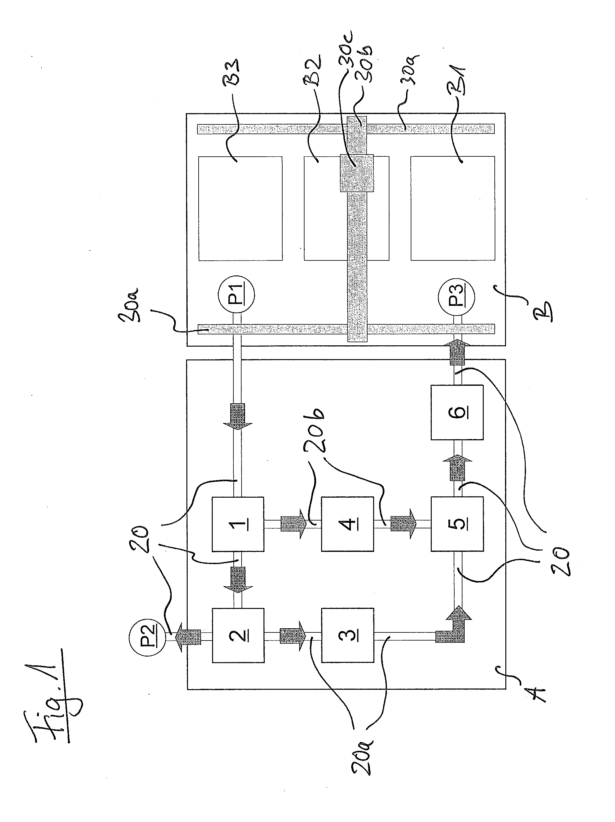
[0069]FIG. 1 shows a schematic top view of a system for producing tubular concrete products in a casting method by means of upright casting molds according to a first exemplary embodiment of the invention.

[0070]In general, all casting molds used in the system have an upright outer mold and a mold core vertically arranged in the upright outer mold. Optionally, the casting molds have at the bottom side a base sleeve which serves as a base for positioning the casting molds and also for locking the outer mold with the mold core. Such base sleeves can be removed or be fixedly mounted on the mold core.

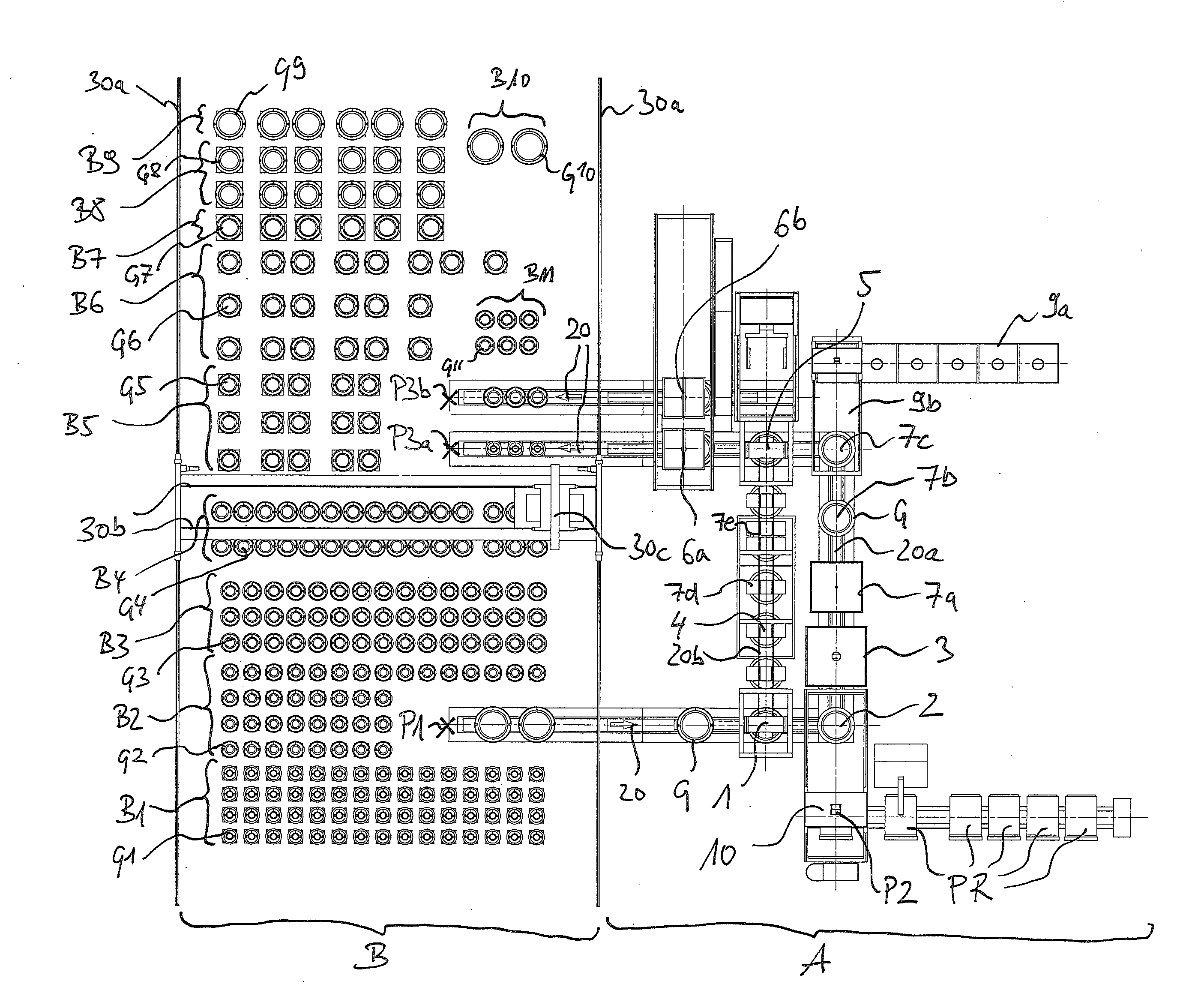
[0071]The system for producing tubular concrete products in a casting method comprises a fabrication zone A having a plurality of fully automated fabrication stations 1 to 6 and a mold conveyor 20 with the mold conveying sections 20a and 20b, which for respective production lines which are carried out in parallel with respect to production technology extend between the fabrication stations 1...

second exemplary embodiment

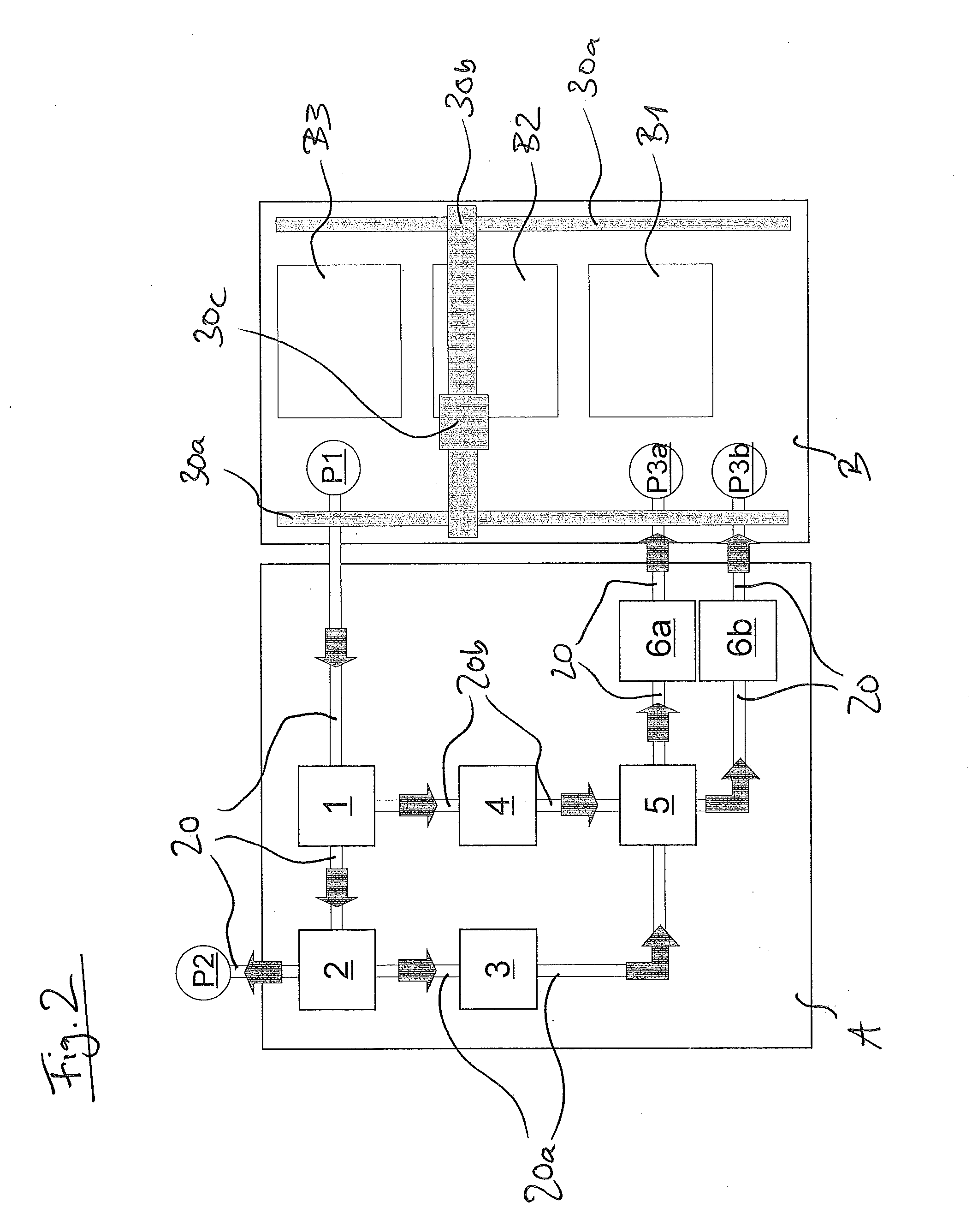
[0088]FIG. 2 shows a schematic top view of a system for producing tubular concrete products in a casting method by means of upright casting molds according to a second exemplary embodiment of the invention.

[0089]Here, the system of the second exemplary embodiment differs from that of the first exemplary embodiment in that along with the first filling station 6a a further filling station 6b is provided. The conveyor 20 in the second exemplary embodiment is adapted to convey a casting mold assembled at the mold assembly station 5 to the first filling station 6a, e.g. if a casting mold is already filled at the second filling station 6b, or to convey it to the second filling station 6b, e.g. if a casting mold is already filled at the first filling station 6a.

[0090]This enables in an advantageous way to reduce the lengths of cycle of the system since the time-consuming operations of filling the casting mold with concrete can be carried out in parallel at two (or in other exemplary embod...

third exemplary embodiment

[0092]FIG. 3 shows a schematic top view of a system for producing tubular concrete products in a casting method by means of upright casting molds according to a third exemplary embodiment of the invention. Here, the system of the third exemplary embodiment differs from that of the first exemplary embodiment in that another optional fabrication station 7 is provided between the mold core cleaning station 3 and the mold assembly station 5.

[0093]For example, it is conceivable to provide at the site of the fabrication station 7 a coating station which is adapted to externally coat a mold core arranged at the coating station after the cleaning, e.g. by means of a separating agent, such as wax, or by means of a separating agent containing fat, such as oil, which could be applied to the mold core by spraying or by sponge application, for example. A similar coating station could be provided in other exemplary embodiments in addition or alternatively for the outer molds in the production lin...


PUM

PropertyMeasurementUnit
Lengthaaaaaaaaaa
Sizeaaaaaaaaaa
Volumeaaaaaaaaaa

Abstract

A method and system for producing tubular concrete products in a casting method using upright casting molds. The system includes a fabrication zone with a plurality of fully automated fabrication stations and a mold conveyor, the first zone having: a first demolding station for removing an outer mold from a casting mold positioned at the first demolding station, a second demolding station for removing a cured tubular concrete product form a mold core positioned at the second demolding station, a mold core cleaning station for cleaning a mold core positioned at the mold core cleaning station, an outer mold cleaning station for cleaning an outer mold positioned at the outer mold cleaning station, a mold assembly station for assembling a casting mold from an outer mold and a mold core, and at least one filling station for filling an assembled casting mold with concrete.

Description

[0001]The present invention relates to a system and method for producing tubular concrete products, in particular concrete tubes, in a casting method by means of upright casting molds, wherein the casting molds each have an upright outer mold and a mold core arranged in the upright outer mold.BACKGROUND OF THE INVENTION[0002]The prior art discloses partly automated plants and systems for producing tubular concrete products, in particular concrete tubes, in which tubular concrete products are produced. The partly automated production of tubular concrete products is here usually conducted by means of the vibration press method using vibration compaction devices or by means of the rotary press method where the compaction and inner shaping of the tubular concrete products is carried out using a roll head. However, the production systems for producing tubular concrete products by means of the vibration press method or the rotary press method are expensive and require a large set-up area ...

Claims


Application Information

Patent Timeline
IPC IPC(8): B28B15/00
CPCB28B15/007B28B15/00B28B17/0063B28B21/04
Inventor SCHLUSSELBAUER, JOHANNSCHLUSSELBAUER, ULRICH
Owner SCHLUSSELBAUER JOHANN
Learn More