
Vibration-Dampening Rod

a technology of vibration-dampening rods and rods, which is applied in the direction of machine supports, other domestic objects, mechanical apparatus, etc., can solve the problems of limited damping of joints and relatively expensive manufacturing processes, and achieve better vibration-damping efficiency and joint production cost saving

Inactive Publication Date: 2015-08-27
HUTCHINSON SA
View PDF17 Cites 6 Cited by
  • Summary
  • Abstract
  • Description
  • Claims
  • Application Information

AI Technical Summary

Benefits of technology

This patent describes a way to connect an inner frame to a ring using only one elastic body, instead of two separate parts. This saves money and improves the efficiency of reducing vibration. The elastic connection allows more material to be used, which results in better performance.

Problems solved by technology

This joint has the following drawbacks:the manufacturing process is relatively expensive because it involves two molding operations to produce the two elastomeric bodies,the vibration damping of the joint is limited, because the amount of elastomer that can be used in the elastic connection between the inner frame and the ring is relatively small due to being produced as two separately molded parts.

Method used


Image

  • Vibration-Dampening Rod
  • Vibration-Dampening Rod
  • Vibration-Dampening Rod

Examples


Embodiment Construction

[0029]In the various figures, the same references designate identical or similar elements.

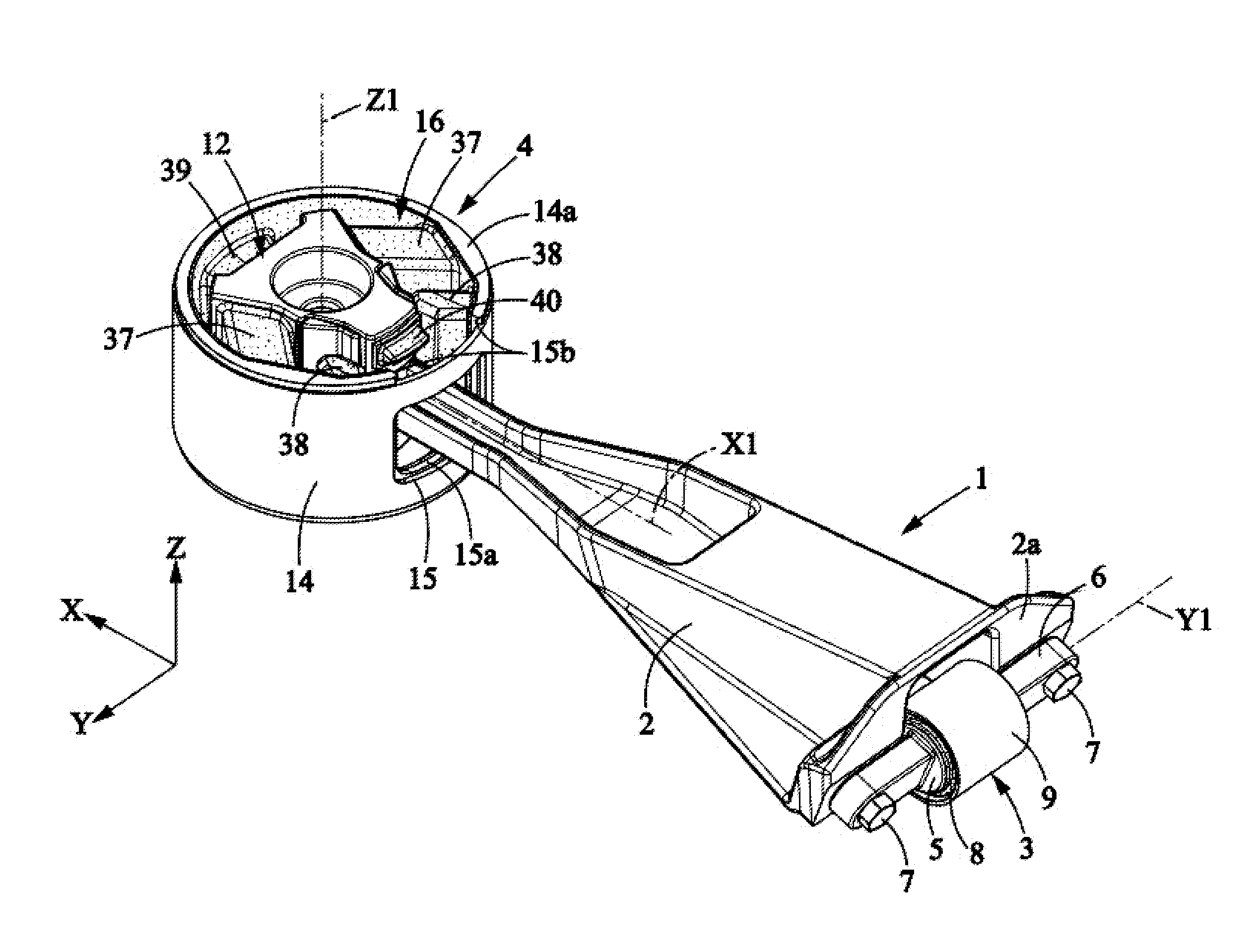
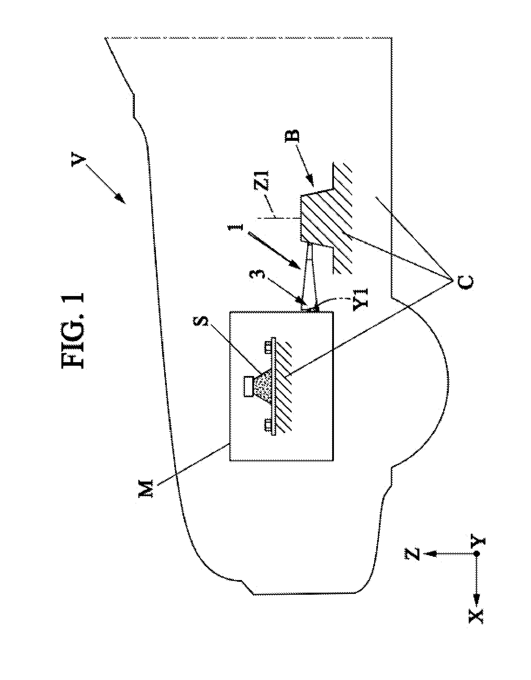
[0030]As is schematically represented in FIG. 1, the invention relates to a vibration-dampening rod 1, in particular a torque reaction rod for a motor vehicle V with an internal combustion engine.

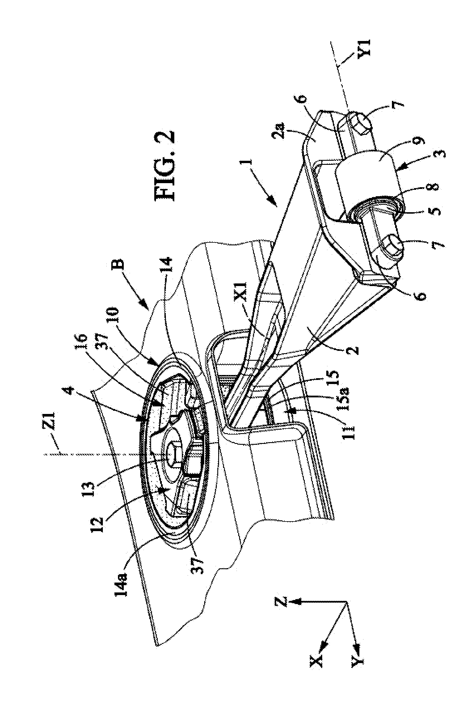
[0031]The rod 1 may be pivotably connected:[0032]to the engine M, about a transverse axis Y1 parallel to the transverse direction Y of the vehicle,[0033]and to the body C of the vehicle, particularly to the subframe B, about a vertical axis Z1.

[0034]The rod 1 is adapted to damp torque from the engine M when the engine is mounted on the body C by a suspension comprising, for example, two vibration-damping engine mounts S aligned in the transverse direction Y of the vehicle.

[0035]As represented in FIGS. 2 to 5, the rod 1 comprises a rigid rod body 2 which extends longitudinally between first and second ends 2a, 2b respectively connected to first and second vibration-dampening joints 3, 4.

[0036]The rod bo...


PUM


Abstract

Vibration-dampening rod comprising a rod body connecting first and second joints. The second joint comprises a ring having a central axis and comprising a through-window, an inner frame surrounded by the ring, and an elastomeric body overmolded on the inner frame and on the inside of the ring, molded as one piece and extending over a major portion of the axial height of the ring. The rod body traverses the window of the ring and is fixed to the inner frame.

Description

FIELD OF INVENTION[0001]The present invention relates to vibration-dampening rods, particularly those for motor vehicles.BACKGROUND OF THE INVENTION[0002]More particularly, the invention relates to a vibration-dampening rod having first and second joints and a rigid rod body extending between first and second ends respectively connected to the first and second joints, the second joint comprising:[0003]a rigid ring having a central axis and extending for a certain axial height, the ring comprising a through-window,[0004]a rigid inner frame surrounded by the ring,[0005]and an elastomeric body overmolded on the inner frame and on the inside of the ring,said rod body traversing said window and the second end of the rod body being fixed to the inner frame.[0006]Document EP-A-1247678 discloses an example of a joint of this type, which is part of a vibration-dampening rod where the rigid rod body traverses said window to attach to the inner frame. In this known joint, the elastic connectio...

Claims


Application Information

Patent Timeline
Patent Type & Authority Applications(United States)
IPC IPC(8): F16F15/08F16M13/02
CPCF16M13/02F16F15/08F16C7/04F16C11/0614F16C11/0695F16C11/083F16F1/3849
Inventor PIZANTI, THIERRYSTAHL, MANFREDPETIT, PASCALLEDOUX, ANTONY
Owner HUTCHINSON SA
Learn More