Dispensing pump

Active Publication Date: 2015-08-27
APTAR ITAL
View PDF3 Cites 4 Cited by
  • Summary
  • Abstract
  • Description
  • Claims
  • Application Information

AI Technical Summary

Benefits of technology

The present invention is for a dispensing pump that prevents liquid from leaking through the venting path while still allowing the pump to work effectively during each stroke. It is easy to assemble and lightweight to use. Its technical effects include improved efficiency, reliability, and cost-effectiveness.

Problems solved by technology

The liquid can therefore go in touch with the metal spring, with a potential risk of corrosion, or even flow outside the dispensing pump, so creating unaesthetic problems, contamination of the liquid and mess.
Furthermore, the liquid that leaks out of the venting passages and stops there for a while, could also dry and clog the venting passages.

Method used


Image

  • Dispensing pump
  • Dispensing pump
  • Dispensing pump

Examples


Embodiment Construction

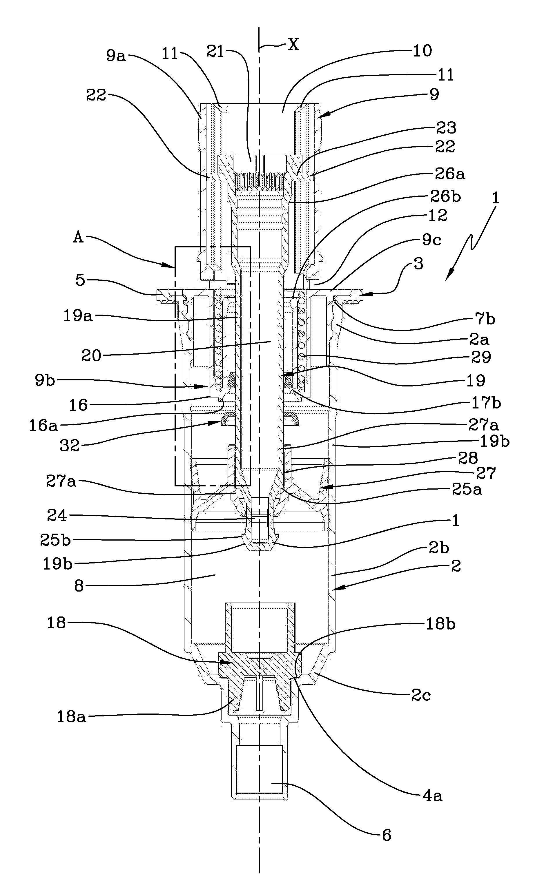
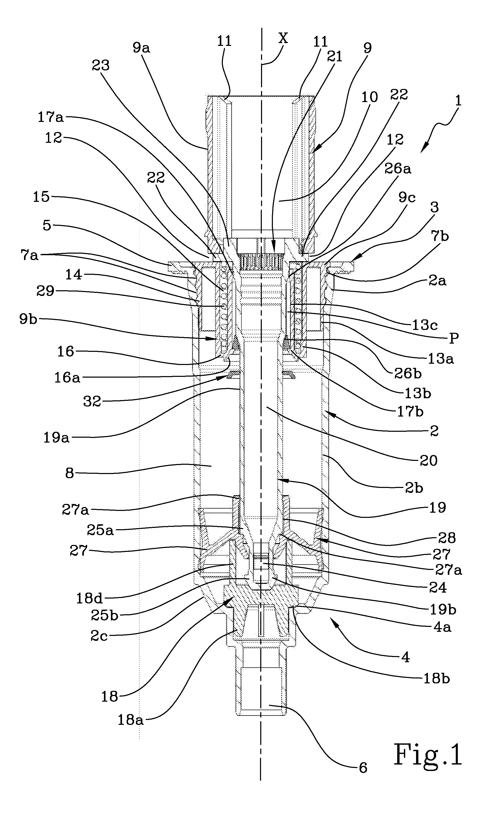
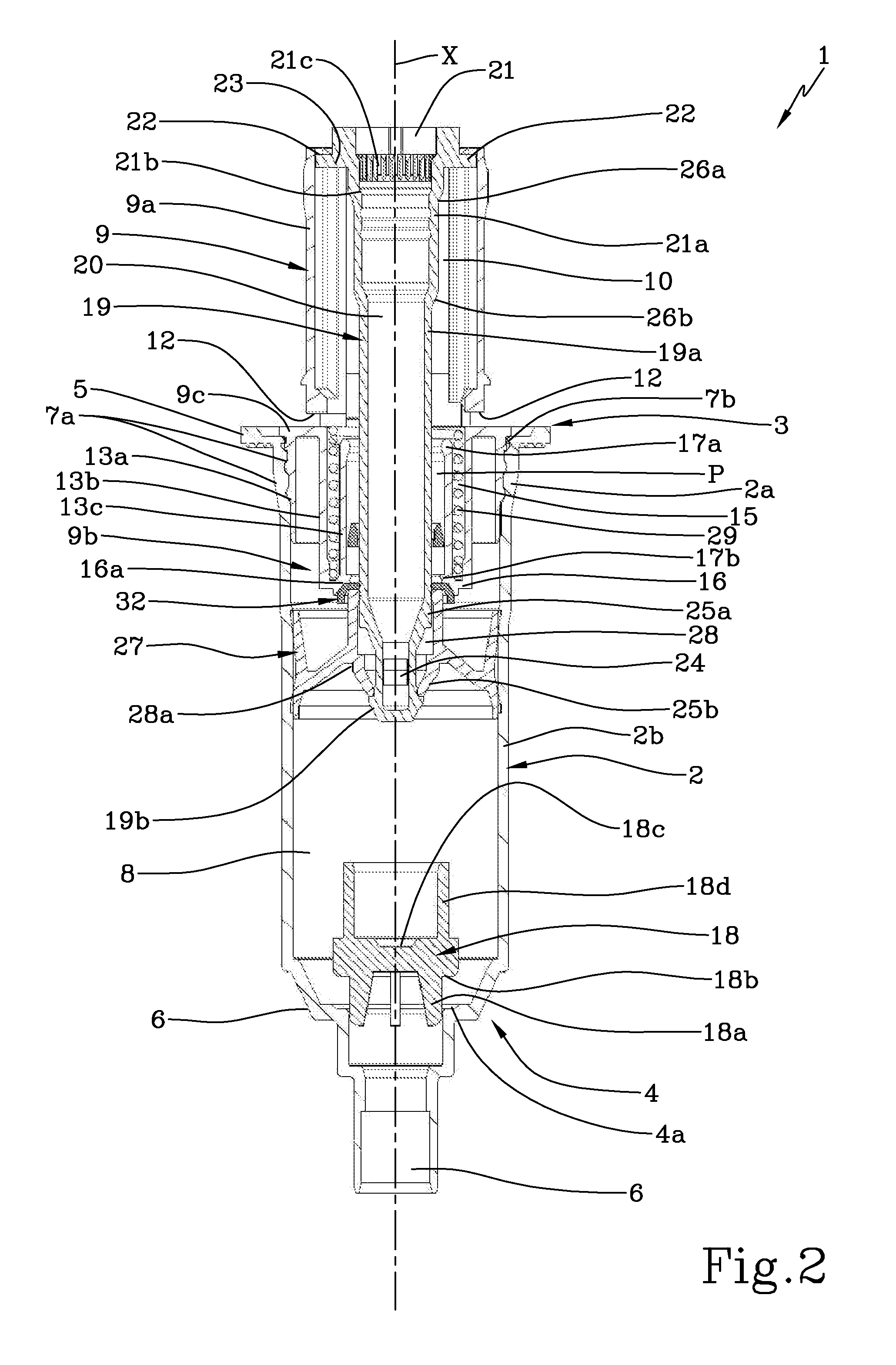
[0019]With reference to the accompanying drawings, a dispensing pump in accordance with the present invention is indicated with the number 1. The dispensing pump can be fastened to a ring nut (not shown) able to be screwed onto the neck of the bottle.

[0020]The dispensing pump 1 comprises a housing 2 in the form of a hollow containment body extending along a longitudinal axis X, able to be inserted in a bottle (not shown). The dispensing pump 1 is disclosed with reference to its working position that is when the longitudinal axis X is vertical. Terms like “upper” or “lower” and similar are used with reference to the working position of the dispensing pump corresponding the position shown in the figures.

[0021]The housing 2 has axial-symmetric geometry and it comprises a top portion 3 and a bottom portion 4, having geometries with different diameter.

[0022]The housing 2 presents substantially funnel-like geometry.

[0023]The upper portion 3 of the housing 2 is open and its function is to ...


PUM


Abstract

A dispensing pump includes a housing extending along a longitudinal axis and configured to be inserted in a bottle. The housing defines a dosing chamber and includes a venting hole. A retaining ring is fastened to the housing and inserted therein. A hollow stem is associated to a piston and inserted in a hole of the retaining ring leaving a passage. The hollow stem and piston are movable between a lowered position and a raised position corresponding to different volumes of the dosing chamber. A venting path includes at least the passage between the hollow stem and the retaining ring and the venting hole. Through the venting path a volume of air enters the bottle through the venting hole during the pump actuation to replace liquid pumped out from the bottle by the pump. A venting valve is interposed between the hollow stem and retaining ring, along the venting path.

Description

TECHNICAL FIELD[0001]The present invention relates to a dispensing pump, i.e. to a pump of a dispenser or dosing device able to be applied to the neck of a bottle to dispense the liquid contained therein.BACKGROUND ART[0002]In order to dispense a liquid contained in a bottle it is known to use a so called “lock down” dispensing pump which, when applied to the bottle and put on the market, is in a down-locked position.[0003]In particular “atmospheric” dispensing pumps the housing of the dispensing pump has on its side a venting hole which function is to permit the venting, i.e. the admission of the air in the bottle. In particular during the pump actuation a volume of air enters into the bottle through the venting hole, in order to replace the liquid pumped out from the bottle by the pump.[0004]A dispensing pump of this type is known for example from EP0990595 or WO2011 / 074024. When this dispensing pump is in its down-locked position, that is the condition in which the dispensing pum...

Claims


Application Information

Patent Timeline
IPC IPC(8): B05B11/00
CPCB05B11/3098B05B11/3001B05B11/3047B05B11/0044B05B11/1002B05B11/1023B05B11/105B05B11/106B05B11/1074B05B11/1098B05B11/1001B05B11/1047
Inventor ZAVARELLA, MARCOCAPORALE, MATTEO
Owner APTAR ITAL
Why Eureka
Try Eureka