Flow channel module and chromatograph provided with the flow channel module

a flow channel module and flow channel technology, applied in the field of flow channel modules and chromatographs, can solve the problems of impaired analysis results and affected peak shape of chromatograms, and achieve the effects of high air tightness, reduced dead volume, and high reproducibility

Active Publication Date: 2015-08-20
SHIMADZU CORP
View PDF4 Cites 0 Cited by
  • Summary
  • Abstract
  • Description
  • Claims
  • Application Information

AI Technical Summary

Benefits of technology

This patent describes a flow channel module used in a gas chromatograph. The module has a protrusion section connected to an outer flow channel, which allows for flat temperature control of the flow channel plate without interfering with its main body. The module also has a pressing mechanism to improve air and liquid tightness at the connection section. This design reduces the need for excess space and helps achieve reliable analysis results. Overall, this patent provides a solution for achieving uniform temperature control and high air tightness in a gas chromatograph.

Problems solved by technology

For example, in the case of using the flow channel plate as a column for separation / analysis such as a gas chromatography or a liquid chromatography, if there is a great dead volume at the connection section especially at the outlet side, the peak shape of the chromatogram is affected, and the analysis result is impaired.

Method used


Image

  • Flow channel module and chromatograph provided with the flow channel module
  • Flow channel module and chromatograph provided with the flow channel module
  • Flow channel module and chromatograph provided with the flow channel module

Examples


Embodiment Construction

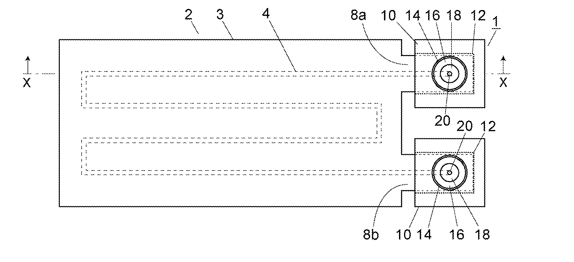
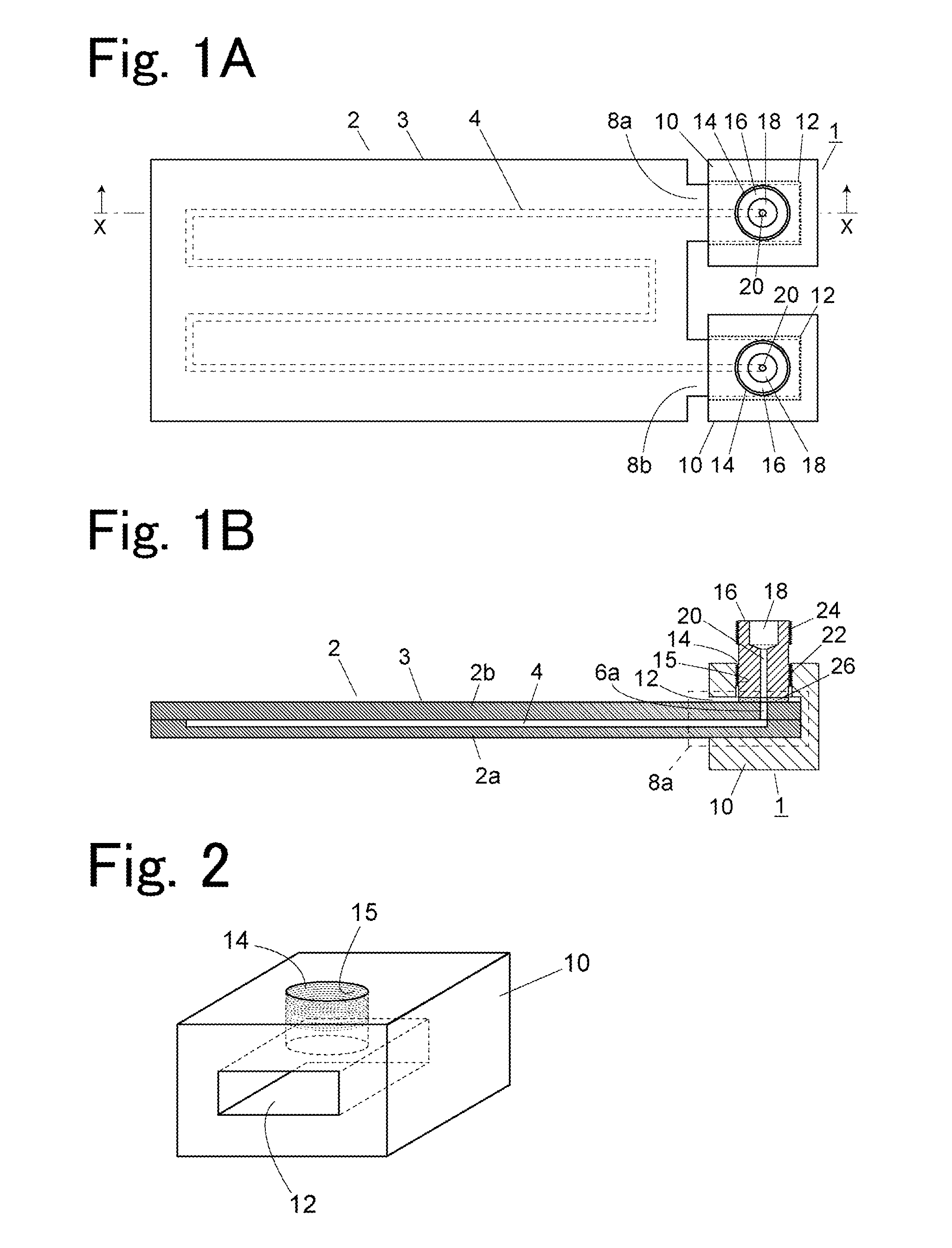
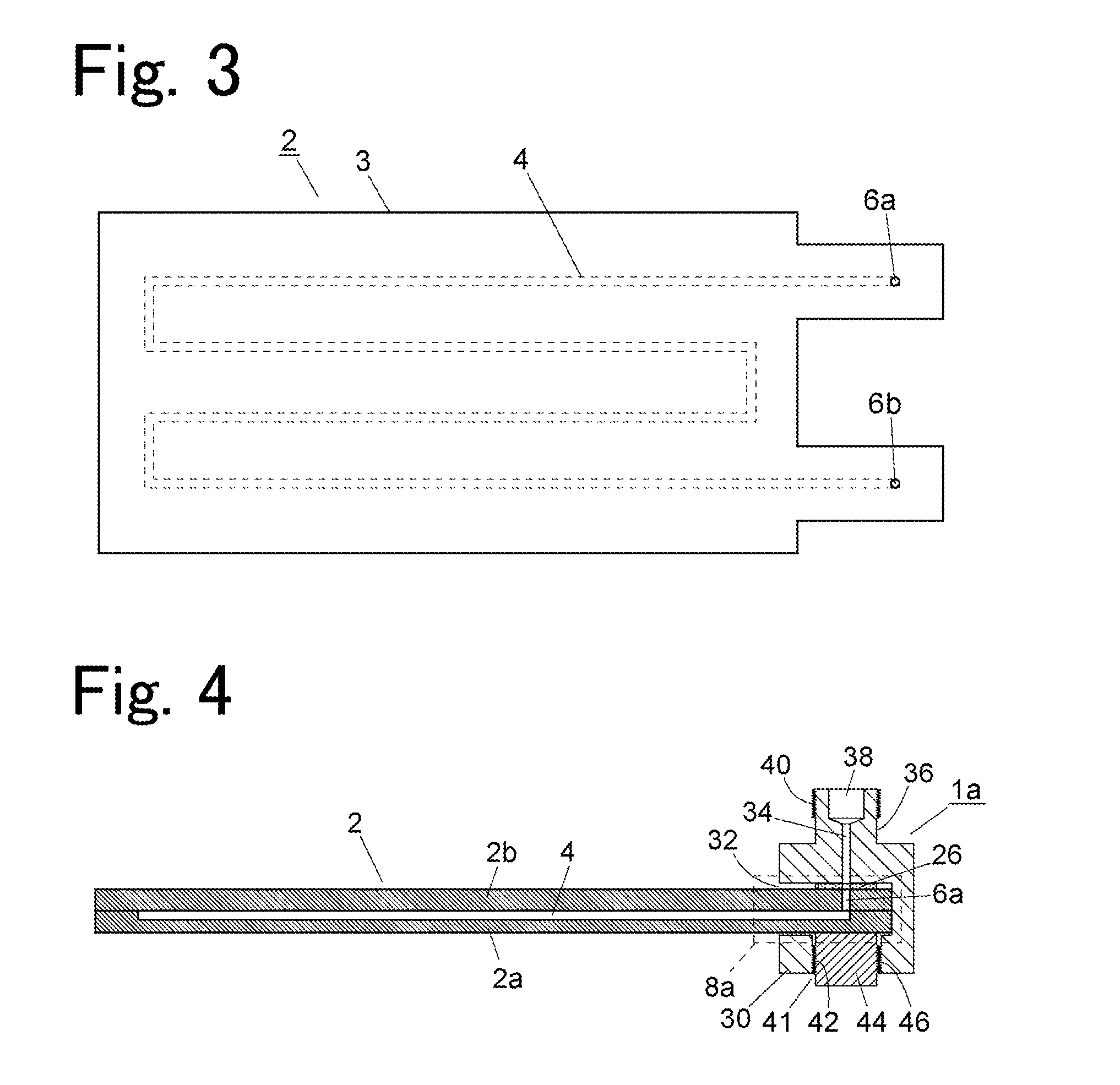
[0030]According to a flow channel module of the present invention, a flow channel connection block may be composed of a block main body and a movable section attached to the block main body. In this case, a concave section may be provided to the block main body, an outer flow channel connection section may be provided to the movable section, the block main body may be provided with a movable section insertion hole which is a hole for inserting the movable section and which penetrates from the surface of the block main body to the concave section, the movable section may be provided with an insertion section that is to be inserted from the tip end into the movable section insertion hole and a tip plane that is provided to the tip end of the insertion section, where the tip plane and the outer flow channel connection section are connected by a flow channel to form a port facing surface, and a pressing mechanism may have a thread tapped on the inner circumferential surface of the movab...


PUM

PropertyMeasurementUnit
thicknessaaaaaaaaaa
widthaaaaaaaaaa
widthaaaaaaaaaa

Abstract

A flow channel module comprises a flow channel plate, a flow channel connection block, and a pressing mechanism. The flow channel plate is provided with a main body and a protrusion section protruding in the circumferential direction from the peripheral edge of the main body, the protrusion section having a port communicating with an inner flow channel. The flow channel connection block is provided with a concave section for being engaged with the protrusion section and having inside a port facing surface for facing the port, and an outer flow channel connection section that is connected to the port facing surface by a flow channel. The pressing mechanism is configured to press the protrusion section inserted in the concave section and the port facing surface against each other so that the flow channel and the port are connected while maintaining air tightness or liquid tightness.

Description

TECHNICAL FIELD[0001]The present invention relates to a flow channel module, and a chromatograph, such as a gas chromatograph or a liquid chromatograph, using the flow channel module as an analytical column.BACKGROUND ART[0002]Conventionally, much research on forming of a fine flow channel structure, and synthesis, separation, analysis, and the like of fluid samples in the flow channel has been conducted, and a micro TAS (Total Analysis System) is widely known in its technical field. As a method of forming a fine flow channel structure, a method of joining two plates to form a flat flow channel plate is generally known. One of the flow channel plates has a groove to be a fine flow channel formed on its surface, and the other plate has through holes formed at positions corresponding to the end portions of the fine flow channel as an outlet and an inlet of the fine flow channel, and the plates are joined with the surface on which the groove is formed arranged on the inside.[0003]To tr...

Claims


Application Information

Patent Timeline
Patent Type & Authority Applications(United States)
IPC IPC(8): G01N30/02G01N33/18G01N33/00
CPCG01N30/6026G01N30/6095Y10T137/598G01N33/0009G01N33/1893G01N30/02
Inventor KANAI, MASAKIMATSUOKA, SATOSHINISHINO, MASANORINISHIMOTO, TAKAHIRO
Owner SHIMADZU CORP
Why Eureka
Try Eureka