Energy absorbing fastening system

a fastening system and energy-absorbing technology, applied in the field of fastening systems, can solve the problem of not being able to guarantee that the cot will still function as it is designed

Inactive Publication Date: 2015-08-20
STRYKER CORP
View PDF13 Cites 2 Cited by
  • Summary
  • Abstract
  • Description
  • Claims
  • Application Information

AI Technical Summary

Benefits of technology

The present invention is a fastening system that reduces the impact energy transferred to a child during an ambulance ride. This helps to protect the child from injury.

Problems solved by technology

Further, when an emergency vehicle is involved in an accident or some sort of impact, the manufacture typically requires replacement of the cot, because without testing and / or inspection the manufacturer cannot guarantee that the cot will still function as it is designed.

Method used


Image

  • Energy absorbing fastening system
  • Energy absorbing fastening system
  • Energy absorbing fastening system

Examples


Embodiment Construction

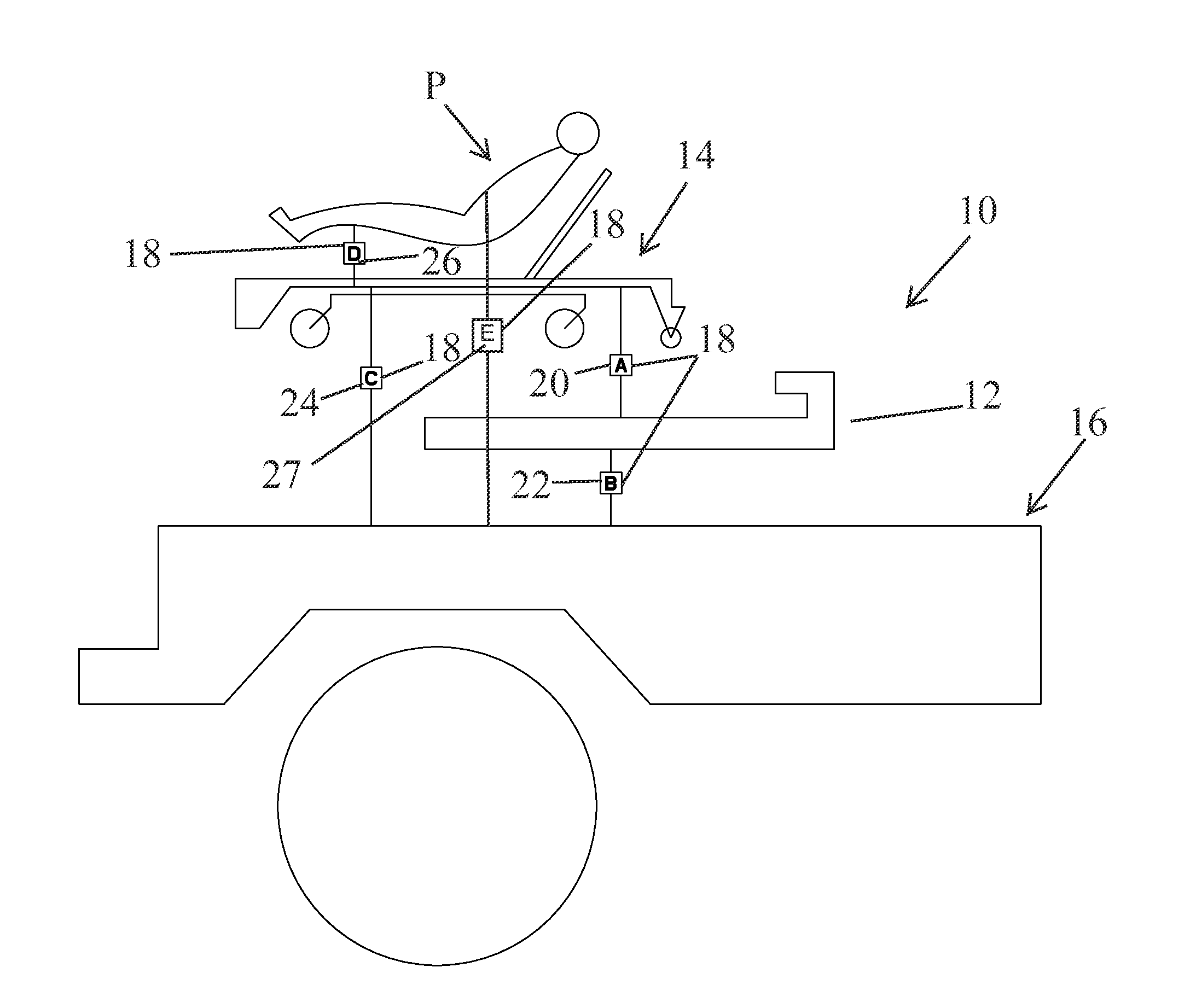
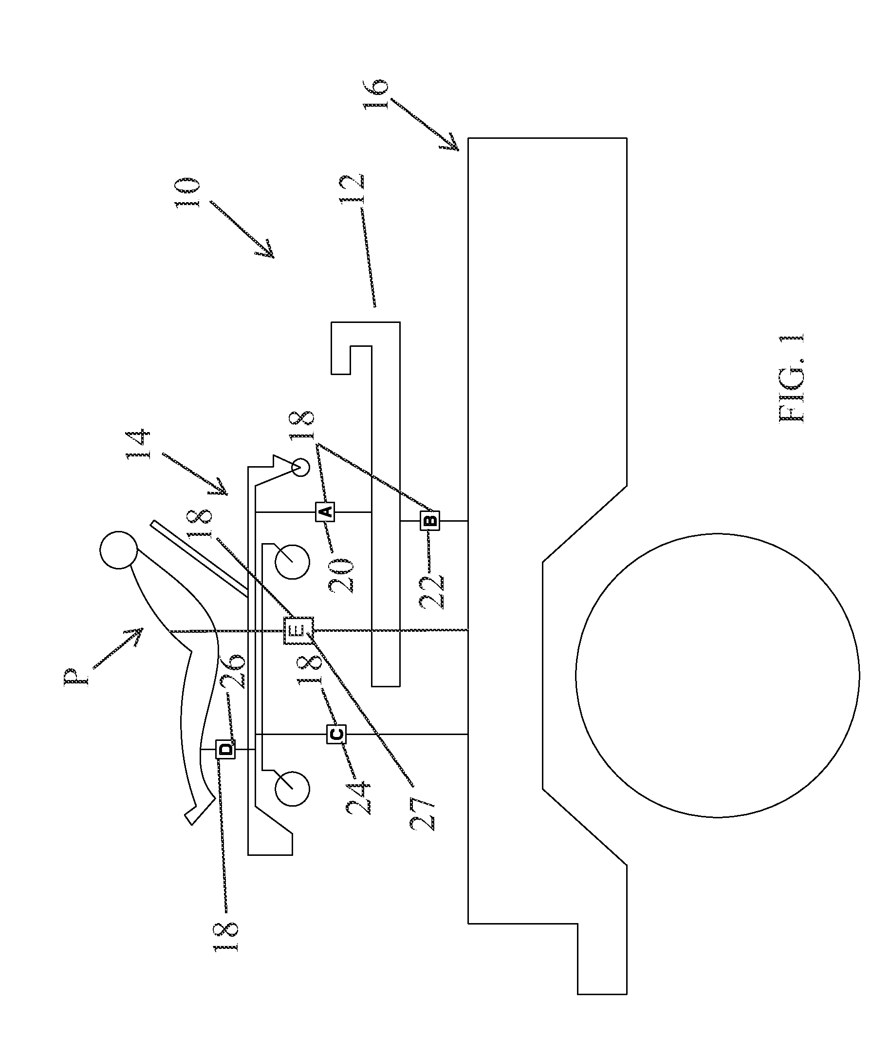
[0045]Referring to FIG. 1, the numeral 10 generally designates a fastening system of the present invention. As will be more fully described below, fastening system 10 is configured to absorb energy when, for example, the vehicle in which the fastening system is mounted is subject to an impact, such as in a crash. Further, fastening system 10 may alternately or in addition incorporate an impact indicator to provide an indication of when such an impact exceeds a predetermined level, such as a predetermined acceptable maximum impact level or simply provides an indication of the level of impact, or the both.

[0046]Referring again to FIG. 1, in the illustrated embodiment fastening system 10 comprises a cot fastening system that includes a base 12 for securing a cot 14 in an emergency vehicle 16, such as an ambulance. For examples of suitable bases that may be used in system 10, reference is made to U.S. Pat. Nos. 6,796,757; 7,478,855; 7,540,547; 7,887,113, and copending application Ser. N...


PUM


Abstract

A fastening system includes an energy absorbing or impact indicator and at least one or more of the following: (1) a fastening base for mounting in an emergency vehicle, (2) a patient support engageable with a base, (3) a patient securement mechanism for securing a patient on a patient support, (4) a patient securement mechanism for securing a patient to a vehicle, (5) a patient support securement mechanism operable to secure a patient support in an emergency vehicle, or (6) a patient support securement mechanism operable to secure a patient support to a base, wherein the energy absorbing or impact indicator is located (1) at the patient securement mechanism, or (2) at the patient support securement mechanism, or wherein the energy absorbing or impact indicator is between (1) the base and the vehicle, (2) the patient support and the base, (3) the patient securement mechanism and the patient support, (4) the patient support and the emergency vehicle, (5) the patient and the emergency vehicle, or (6) the patient securement mechanism and the emergency vehicle, wherein the energy absorbing device or impact indicator has at least an energy absorbing state and a rigid state or indicates a level of impact at or between any of the respective component or components.

Description

[0001]The present application is a continuation of Ser. No. 13 / 712,303, filed Dec. 12, 2012, which claims the benefit of an ENERGY ABSORBING FASTENING SYSTEM, Ser. No. 61 / 569,980, filed Dec. 13, 2011, which are hereby incorporated by reference herein in their entirety.TECHNICAL FIELD AND BACKGROUND OF THE INVENTION[0002]The present invention generally relates to a fastening system, and more particularly to a fastening system for use in an emergency vehicle, such as a cot fastening system in an ambulance.[0003]Cot fastening systems are typically rigid structures that keep the cot mounted in the emergency vehicle so that if the emergency vehicle suffers an impact, the cot will remain in the vehicle. To assure the safety of the patient, most countries have developed standards that ensure that the average patient is still retained by the system, even in the event of an impact. In the event of a peak impact, therefore, essentially all the energy is transmitted to the patient, the restrai...

Claims


Application Information

Patent Timeline
Patent Type & Authority Applications(United States)
IPC IPC(8): G01L5/00A61G3/08
CPCG01L5/0052A61G3/006A61G3/0218A61G3/0875A61G2203/30G01L5/00
Inventor MISIKIR, LAIKELAMBARTH, CLIFFORD EDWINMALLAPRAGADA, VISHNUDACEY, IV, ALFRED JAMESBUFFINGA, KEITH
Owner STRYKER CORP
Why Eureka
Try Eureka