
Camera-based visual adjustment of a movable x-ray imaging system

a x-ray imaging system and camera-based technology, applied in the direction of radiation beam directing means, medical science, diagnostics, etc., can solve the problems of workflow limitations, increased equipment clutter in the operation room, and increased equipment costs, so as to facilitate alignment and positioning and reduce hardware requirements

Active Publication Date: 2015-08-20
KONINKLJIJKE PHILIPS NV
View PDF7 Cites 7 Cited by
  • Summary
  • Abstract
  • Description
  • Claims
  • Application Information

AI Technical Summary

Benefits of technology

The present invention is a system and method for aligning an X-ray imaging system quickly and easily. It uses a reference point or image to show the difference between the actual position and the desired position, allowing for intuitive positioning of the X-ray source. The method uses simple equipment, such as a camera, and does not involve any complicated image processing steps. The technical effects of this invention include a reduction in hardware requirements and an easier and more intuitive operation of the X-ray imaging system.

Problems solved by technology

However, it has been shown that external position tracking devices mean additional equipment costs and increased equipment clutter in the operation room and sometimes even have workflow limitations.
However, integrated sensors also mean additional costs and require the operator's attendance and knowledge for aligning and positioning.

Method used


Image

  • Camera-based visual adjustment of a movable x-ray imaging system
  • Camera-based visual adjustment of a movable x-ray imaging system
  • Camera-based visual adjustment of a movable x-ray imaging system

Examples


Embodiment Construction

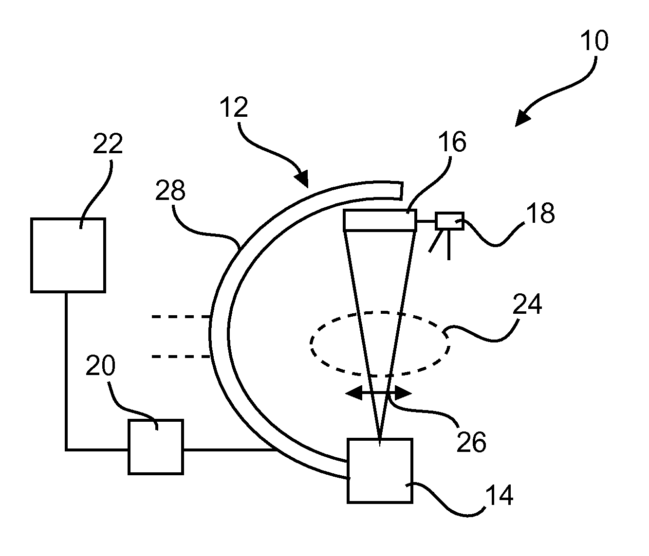
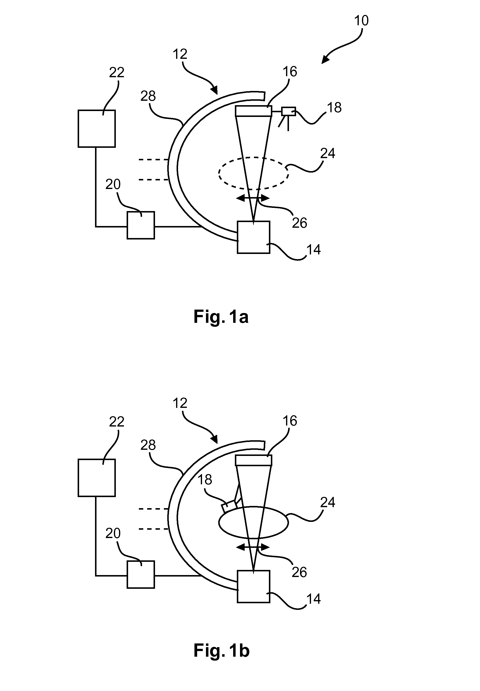
[0051]FIG. 1 shows a movable X-ray imaging system 10 for aligning an object of interest in an X-ray imaging arrangement in relation to each other. The system comprises an X-ray imaging arrangement 12 with an X-ray source 14 and an X-ray detector 16. Further, at least one camera 18 is provided, together with a data processor 20 and a display 22. In FIG. 1A, the camera 18 is attached to the X-ray imaging arrangement. In FIG. 1B, the same reference numbers have been used for the same features of the movable X-ray imaging system 10. In FIG. 1B, the at least one camera 18 is attachable to an object of interest 24.

[0052]With reference to both examples, the at least one camera 18 is configured to provide a first image of at least one reference point. The data processor 20 is configured to relate the first image to first projection parameters of a first X-ray image of the object of interest in relation to the object. The projection parameters relate to different degrees of freedom and compr...


PUM


Abstract

The present invention relates to the adjustment of movable X-ray imaging systems. In order to provide a facilitated alignment and positioning for a movable X-ray imaging system with reduced hardware requirements and allowing an intuitive operation, a movable X-ray imaging system (10) for aligning an object of interest and an X-ray imaging arrangement in relation to each other is provided. The system comprises an X-ray imaging arrangement (12) with an X-ray source (14) and an X-ray detector (16), at least one camera (18), a data processor (20), and a display (22). The at least one camera i) is either attached to the X-ray imaging arrangement or ii) is attachable to the object of interest. The at least one camera is configured to provide a first image of at least one reference point. The data processor is configured to relate the first image to first projection parameters of a first X-ray image of the object of interest in relation to the object. The projection parameters relate to different degrees of freedom and comprise at least one of the group of spatial projection position, distance to the object, viewing direction or projection angle, and viewing field. For an acquisition of at least one further X-ray image in a projection coincident with the first projection parameters of the first X-ray image, the display is configured to display at least a graphical representation of the at least one reference point in the first image at least partly overlaid with an actual image provided by the at least one camera to guide an alignment movement of the X-ray source and / or the X-ray detector and the object in relation to each other after an intermediate displacement.

Description

FIELD OF THE INVENTION[0001]The present invention relates to the adjustment of movable X-ray imaging systems, and relates in particular to a movable X-ray imaging system for aligning an object of interest and an X-ray imaging arrangement in relation to each other, a method for alignment in X-ray imaging, as well as to a computer program element and a computer readable medium.BACKGROUND OF THE INVENTION[0002]In movable X-ray imaging systems, for example mobile C-arm systems, the positioning is of importance for optimal image quality and also for the ease of use. As an example, during an operation or intervention, the X-ray imaging system can be moved at least partially for different purposes. For example, a fluoroscopy projection image is acquired, and the X-ray imaging system is moved to a different position afterwards in order to provide free space for the operation procedure. The X-ray imaging system can also be moved to a different position for acquiring different images from dif...

Claims


Application Information

Patent Timeline
IPC IPC(8): A61B6/00
CPCA61B6/4405A61B6/587A61B6/4441A61B6/08A61B6/463A61B6/547
Inventor BELEI, PETER
Owner KONINKLJIJKE PHILIPS NV
Learn More