Eureka AIR delivers breakthrough ideas for toughest innovation challenges, trusted by R&D personnel around the world.

Model predictive control with reference tracking

a predictive control and reference tracking technology, applied in the direction of motor/generator/converter stopper, dynamo-electric converter control, instrumentation, etc., can solve the problems of inability to control the power converter directly with long horizons, computationally challenging, and even infeasibl

Active Publication Date: 2015-08-13
ABB (SCHWEIZ) AG
View PDF17 Cites 24 Cited by
  • Summary
  • Abstract
  • Description
  • Claims
  • Application Information

AI Technical Summary

Benefits of technology

This patent describes a method and algorithm for efficiently solving the problem of predicting the future behavior of an electrical converter's current and voltage. By using sphere decoding and solving the problem with long prediction horizons, the method achieves low current harmonic distortions and fast transient response times. The cost function used in the method is based on a matrix equation with a triangular matrix, which can be calculated offline and stored in a controller. When implemented, the method provides improved trade-offs between current THD and average switching frequency, and achieves the performance of optimized pulse patterns in transient operation. Overall, this method offers efficient and improved control over electrical converters.

Problems solved by technology

However, this may increase the complexity of these systems and may make the control of switching power converters inherently difficult.
Unfortunately, direct MPC with long horizons for control of power converters may be computationally challenging, or even infeasible, since the number of possible switching sequences grows exponentially as the horizon length is increased.
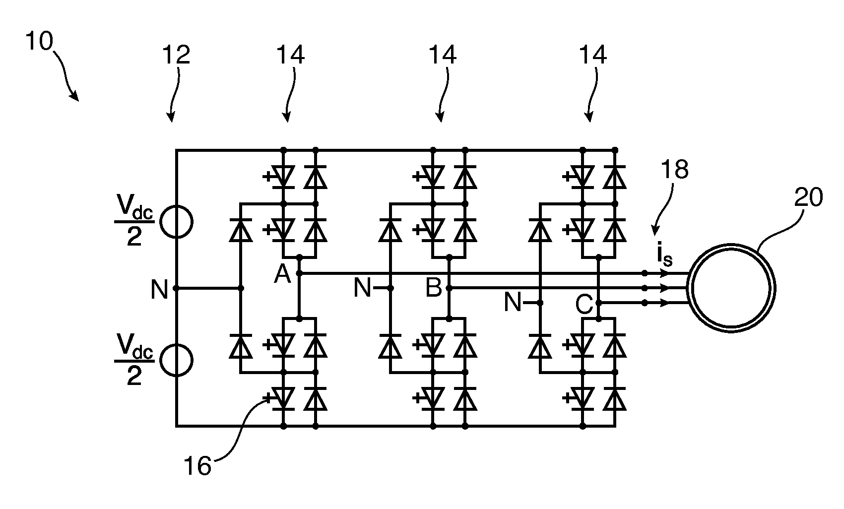
Exhaustive enumeration may not be practical for problems with thousands of sequences, which may arise from direct MPC with prediction horizons of four or more.

Method used


Image

  • Model predictive control with reference tracking
  • Model predictive control with reference tracking
  • Model predictive control with reference tracking

Examples


Embodiment Construction

[0016]Exemplary embodiments of the present disclosure reduce switching costs of an electrical converter to enhance the efficiency of an electrical converter, and to achieve very fast dynamic responses during transients.

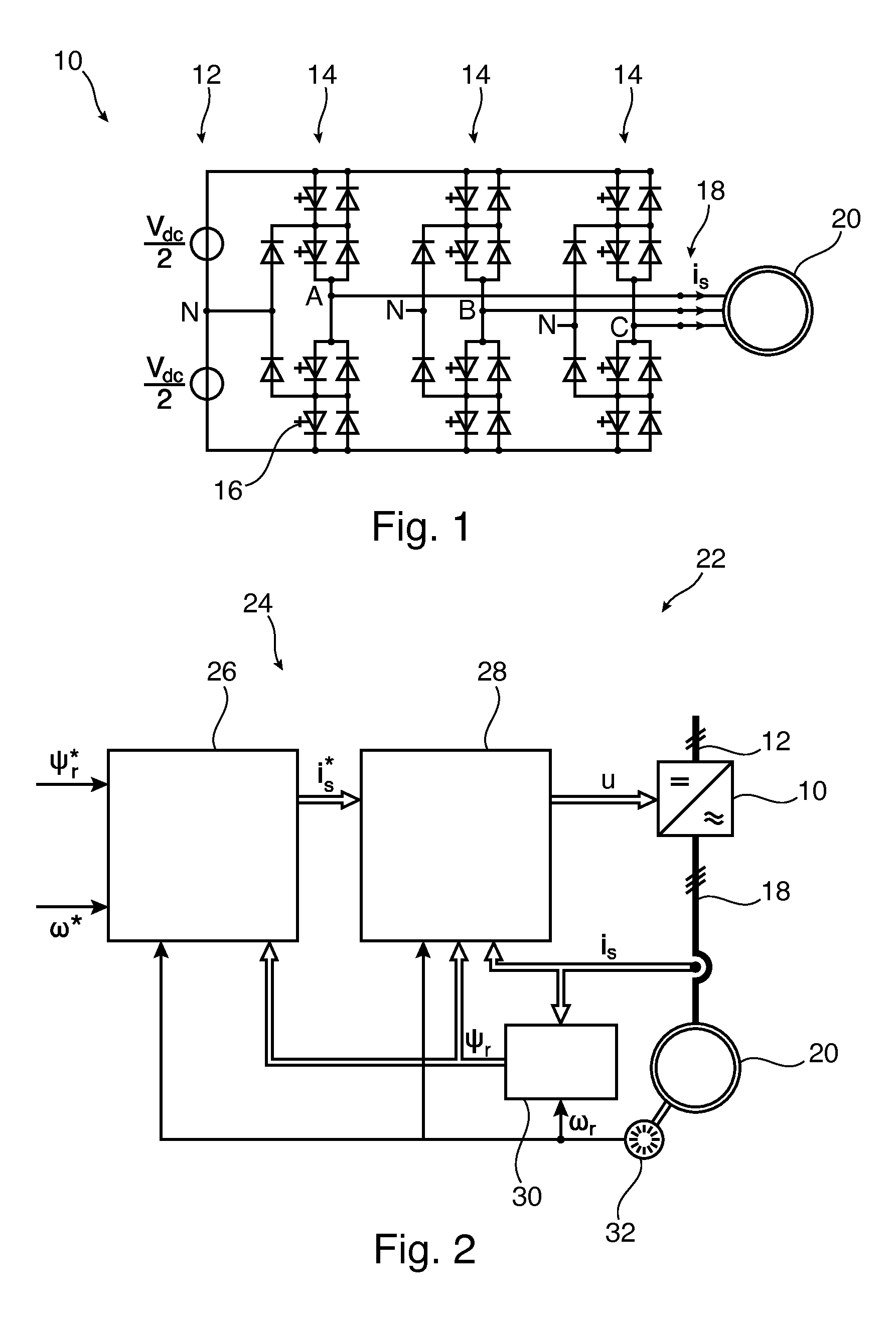
[0017]An exemplary embodiment of the present disclosure relates to a method for controlling an electrical converter. For example, the method, which may be an algorithm completely implemented in a controller, may be adapted (e.g., configured) for controlling a system having the electrical converter supplying an electrical machine (such as an induction motor), while the machine is running at a variable speed.

[0018]The electrical converter may include a plurality of semiconductor switches, wherein the electrical converter is configured for generating a multi-level output voltage from an input voltage by switching the plurality of semiconductor switches.

[0019]The exemplary method may be directly applicable to both the machine-side converter in an AC drive setting, as well...


PUM


Abstract

An exemplary electrical converter includes a plurality of semiconductor switches. The electrical converter is configured for generating a two-level or multi-level output voltage from an input voltage by switching the plurality of semiconductor switches. A method for controlling the electrical converter includes receiving a reference electrical quantity (iS*) and an actual electrical quantity (iS), determining a sequence of future electrical quantities of the electrical converter from the actual electrical quantity, determining a maximal cost value based on the sequence of future electrical quantities, and iteratively determining an optimal switching sequence for the electrical converter. A switching sequence includes a sequence of future switching states for the semiconductor switches of the electrical converter. The method also includes selecting the first switching state of the optimal switching sequence as the next switching state (u) to be applied to the semiconductor switches of the electrical converter.

Description

RELATED APPLICATION(S)[0001]This application claims priority as a continuation application under 35 U.S.C. §120 to PCT / EP2013 / 072146, which was filed as an International application on Oct. 23, 2013 designating the U.S., and which claims priority to European Application 12189564.3 filed in Europe on Oct. 23, 2012. The entire contents of these applications are hereby incorporated by reference.FIELD[0002]The present disclosure relates to the field of power converters, and particularly to a method and a controller for controlling an electrical converter, an electrical converter, and an electrical system comprising an electrical converter.BACKGROUND INFORMATION[0003]Electrical power converters are used in a wide range of applications, including variable speed drives, grid-connected power converters, and DC-to-DC converters. There are several methods for controlling electrical converters. One such method is current control with reference tracking for switching power converters, in which ...

Claims


Application Information

Patent Timeline
Patent Type & Authority Applications(United States)
IPC IPC(8): H02M7/483H02P23/00
CPCH02P23/00H02M7/483H02M7/487H02P21/0017H02P27/12H02P27/14
Inventor QUEVEDO, DANIELGEYER, TOBIAS
Owner ABB (SCHWEIZ) AG
Why Eureka
Eureka Blog
Learn More