
Battery System and Motor Vehicle

Inactive Publication Date: 2015-08-13
ROBERT BOSCH GMBH +1
View PDF8 Cites 24 Cited by
  • Summary
  • Abstract
  • Description
  • Claims
  • Application Information

AI Technical Summary

Benefits of technology

[0027]In accordance with a preferred configuration of the invention, the battery system is designed to cool and/or heat the at least one battery cell by means of the thermoelectric element. Owing to the thermoelectric effect, the temperature of the at least one battery cell is regulated depending on the current flow and the direction of current flow through the thermoelectric element. As a result, the thermoelectric effect is used for temperature regulation, in particular by means of cooling. Cooling or heating (for example in the case of cold starting) using the same thermoelectric element is possible depending on the direction of current flow. For this, further electrical or electronic component parts which are customary to a person skilled in the art can als

Problems solved by technology

At temperatures above 120° C., there is the risk of thermal runaway, i.e. an exothermic decomposition reaction of the cell.
In particular thermal management systems operating using a cooling fluid are technically complex, requiring that reliability and safety are ensured, such as, for example, that requirements in respect of density, heat transfers and regulation are met.
The additional weight as a result of the cooling system and a cooling energy required for this can decrease the range.
This is associated with a high level of complexity since a complete cooling system which comprises a heat exchanger, coo

Method used


Image

  • Battery System and Motor Vehicle
  • Battery System and Motor Vehicle
  • Battery System and Motor Vehicle

Examples


Example

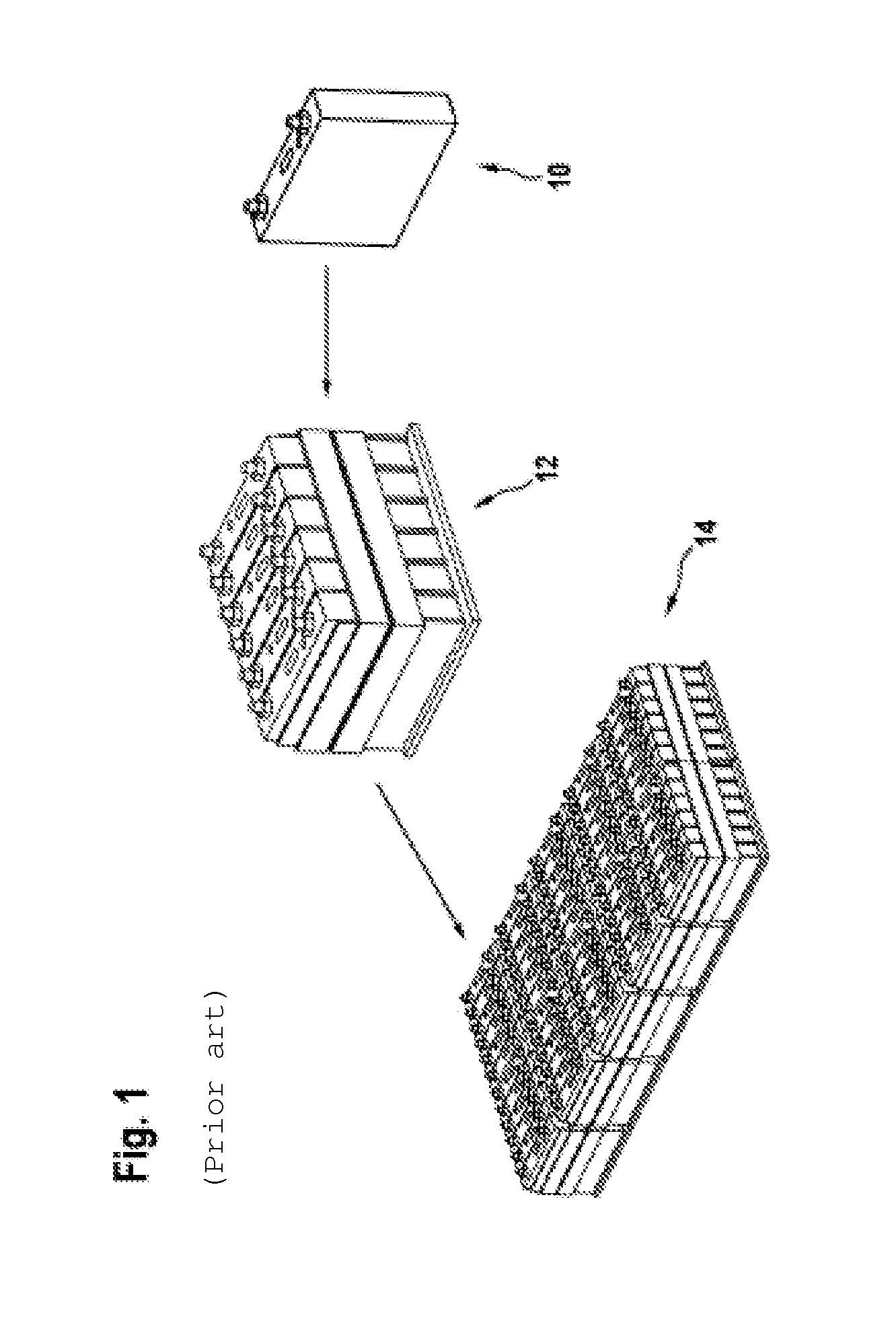
[0038]Details of FIG. 1 have already been given when explaining the prior art.

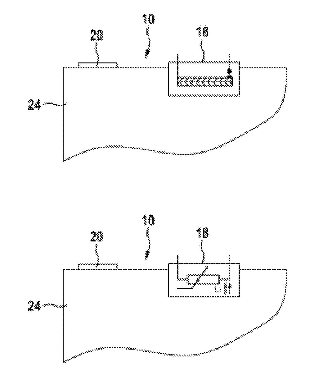
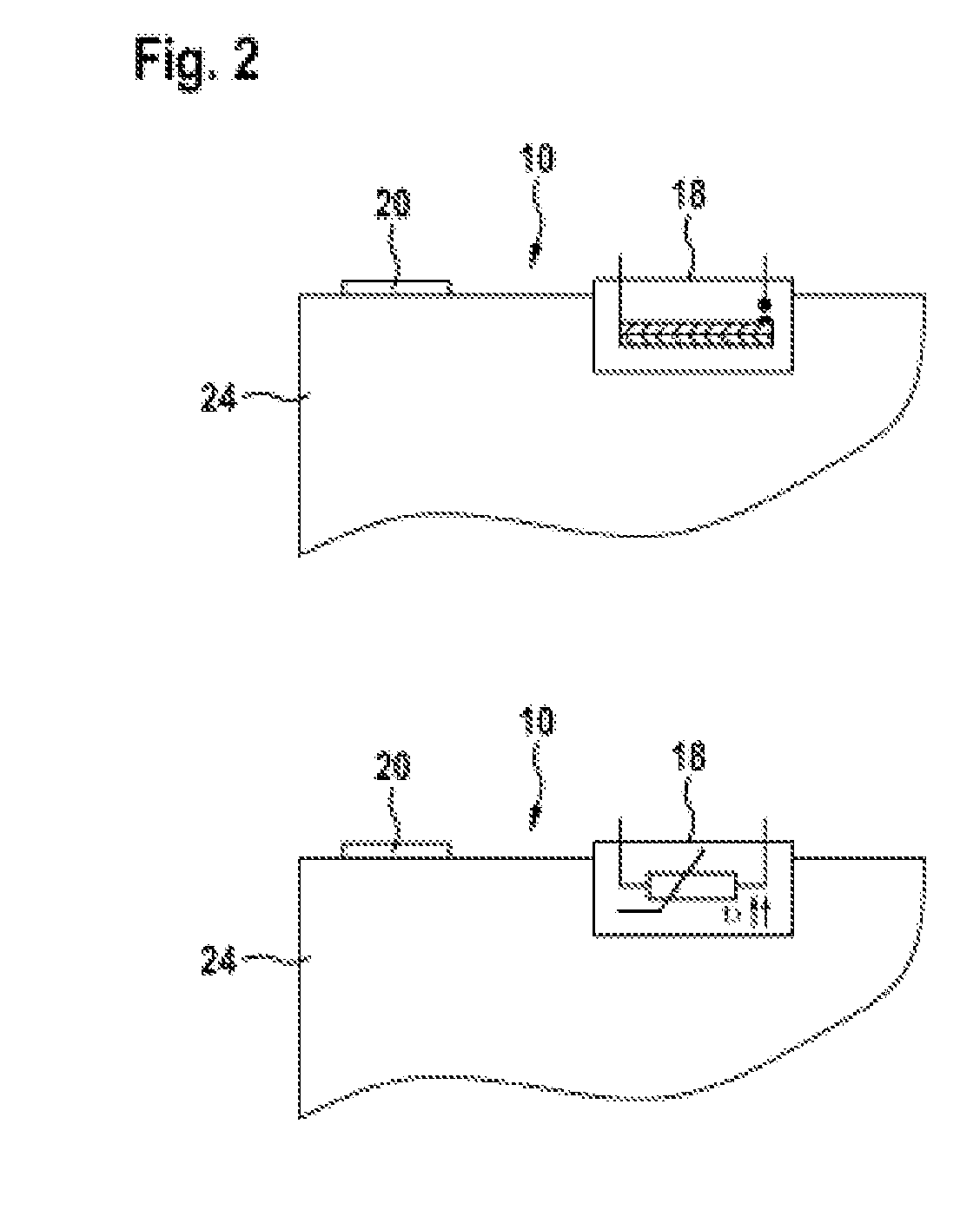
[0039]FIG. 2 shows, schematically, two variants of thermally controllable means for influencing a current flow 18. Said means are used, in conjunction with a thermoelectric element 16, for controlling and / or regulating temperature control. In each case a detail of a battery cell 10 is illustrated, said battery cell comprising a battery cell housing 24 and pole terminals 20 (cell terminals), wherein the pole terminals 20 can be electrically insulated from the battery cell housing 24 by means of an insulator 22. The thermally controllable means for influencing a current flow 18 can be thermally conductively connected to the battery cell 10, in particular to the battery cell housing 24, typically fitted thereon.

[0040]In addition, the thermally controllable means for influencing a current flow 18 can also be thermally conductively connected to a battery module 12, a subunit or a battery 14, which comprise the ...


PUM


Abstract

A battery system includes at least one at least one battery cell, a thermoelectric element, and a thermally controllable device configured to influence a current flow. The thermoelectric element and the thermally controllable device are thermally coupled to the at least one battery cell. The thermoelectric element and the thermally controllable device are connected in series.

Description

[0001]The present invention relates to a battery system comprising at least one battery cell, a thermoelectric element and a thermally controllable means for influencing a current flow, wherein the thermoelectric element and the thermally controllable means for influencing a current flow are thermally coupled to the battery cell. In addition, the invention relates to a motor vehicle comprising the battery system according to the invention.PRIOR ART[0002]It is becoming apparent that, in the future, new battery systems which are subject to very stringent requirements in respect of reliability, safety, performance and life will be used as energy stores both in stationary applications, such as wind turbines, in motor vehicles in the form of hybrid or electric motor vehicles and in (mobile) devices, such as laptops, mobile telephones or power tools. Owing to relatively high energy densities, in particular lithium-ion batteries are used for these applications.[0003]FIG. 1 shows how a plur...

Claims


Application Information

Patent Timeline
IPC IPC(8): H01M10/6572H02J7/00
CPCH01M10/6572H01M10/613H01M10/615H01M2200/106H02J7/0013H01M2200/105H01M10/625B60L1/02B60L3/0046B60L3/04B60L3/12B60L2240/545B60L2240/547B60L2240/549B60L2260/56B60L50/64B60L58/21B60L58/26B60L58/27H01M2200/101H01M2220/20B60L58/15Y02E60/10Y02T10/70
Inventor GLESS, MICHAEL
Owner ROBERT BOSCH GMBH
Learn More