Integrated complex electrode cell having inner seal structure and redox flow cell comprising same

a complex electrode and redox flow battery technology, applied in the direction of regenerative fuel cells, fuel cells, indirect fuel cells, etc., can solve the problems of increasing the volume of the stacked body (i.e. a stack), increasing the amount of material to be used, increasing the cost and stacking time, etc., to achieve the effect of reducing the volume of the stacked body of the redox flow battery, simplifying the stacking process, and increasing the stacking efficiency

Inactive Publication Date: 2015-08-06
KOREA INST OF ENERGY RES
View PDF1 Cites 8 Cited by
  • Summary
  • Abstract
  • Description
  • Claims
  • Application Information

AI Technical Summary

Benefits of technology

[0020]The above described integrated complex electrode cell according to the present invention is advantageous in that the stacking efficiency is increased and the stacking process is simplified as well since the volume of the stacked body of the redox flow battery is significantly reduced by eliminating the bipolar plate frames being used in the prior art. This can be achieved by integrating the bipolar plate between the two manifolds using the resting seats formed therein.
[0021]Thus, a redox flow battery according to the present invention is advantageous in that a redox flow battery of an increased capacity compared with a redox flow battery of the prior art can be provided considering the capacity per unit volume.
[0022]Further, a redox flow battery according to the present invention is advantageou...

Problems solved by technology

When stacking such redox flow batteries of the prior art, a first manifold 21, the frame 11 comprising a bipolar plate, and the second manifold 22 are repeatedly stacked with respect to the separating membrane 30, thus not only the volume of the stacked body (i.e. a stack) is increased but also the amount of the material to be used is increased, thereby causing the problems of i...

Method used


Image

  • Integrated complex electrode cell having inner seal structure and redox flow cell comprising same
  • Integrated complex electrode cell having inner seal structure and redox flow cell comprising same
  • Integrated complex electrode cell having inner seal structure and redox flow cell comprising same

Examples


experimental example

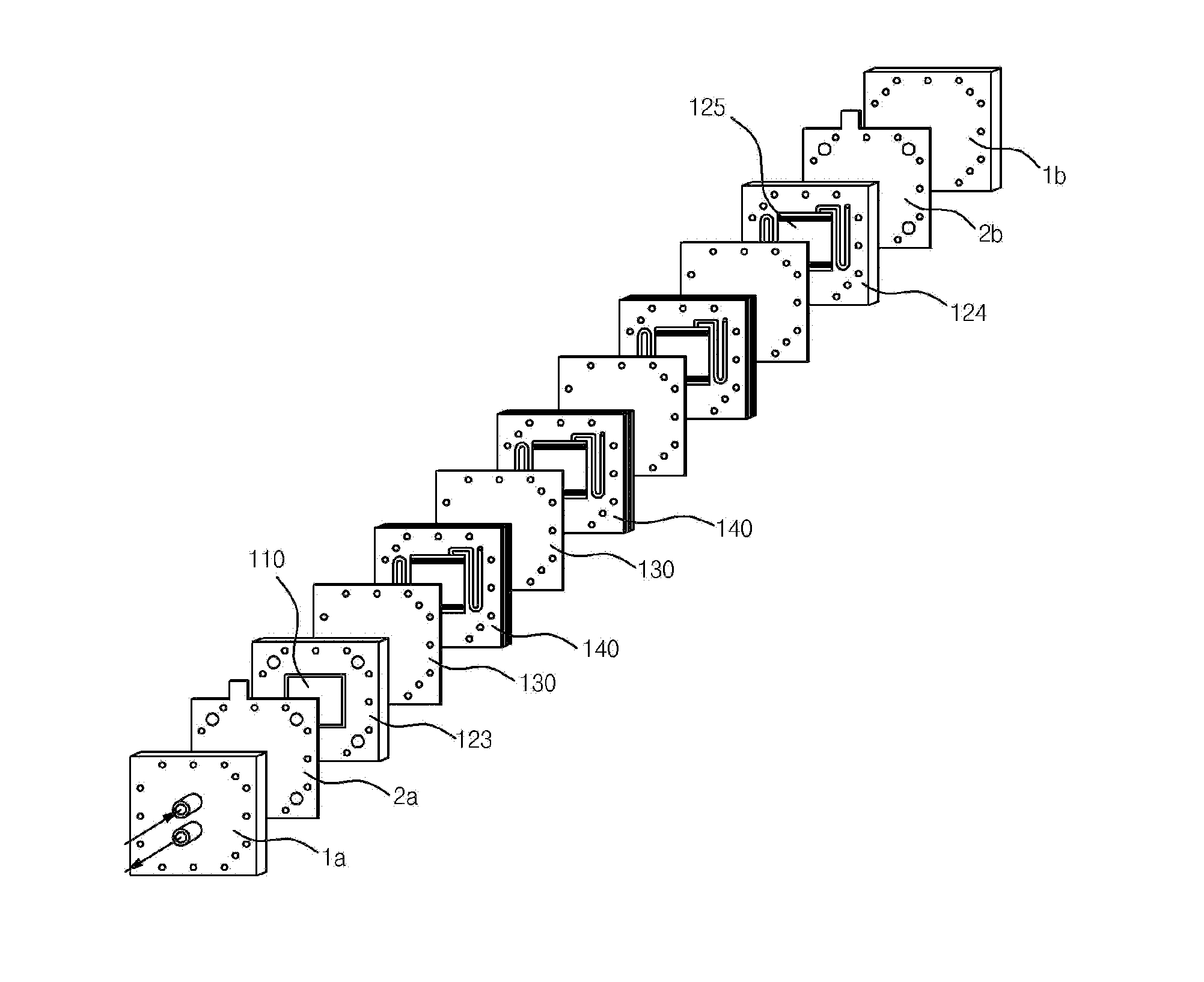
[0073]A redox flow battery having a structure, as illustrated in FIG. 2, has been constructed in order to verify the crossing-over phenomenon of the positive and the negative electrolytes through the bipolar plate (graphite conductive plate, GCP). However, non-porous hard PVC is used instead of the separating membrane in order to exclude the crossing-over phenomenon of the electrolyte through the separating membrane. A 5 mm thick graphite fiber sheet is used as an electrode, and cells are constructed by cutting the graphite fiber sheet to have an area of 30 cm2. At this time, as illustrated in FIG. 7, the integrated complex electrode cell is constructed to have a structure wherein the O-rings are separately formed in the first manifold and the second manifold respectively.

[0074]In addition, a positive electrolyte tank, a negative electrolyte tank, and a pump are provided for enabling the flow of the electrolyte of a redox flow battery. In the positive electrolyte tank, 2 moles of va...


PUM


Abstract

A laminated structure of a redox flow cell, an integrated complex electrode cell, and a redox flow cell comprising same, wherein the integrated complex cell can reduce stack lamination process time and lamination cost and increase lamination efficiency by integrating a manifold and a bipolar plate in order to facilitate lamination. The integrated complex electrode cell having an inner seal structure, which inhibits the overflow of electrolytes, is characterized in that it inhibits the overflow of electrolytes of positive and negative poles by forming a structure in which an integrated part of the manifold and the bipolar plate can be sealed.

Description

TECHNICAL FIELD[0001]The present invention relates to an integrated complex electrode cell capable of increasing the stacking efficiency, and a seal structure provided for preventing the overflow of the electrolytes inside the integrated complex electrode cell, and a redox flow cell comprising an integrated complex electrode cell having the inner seal structure.BACKGROUND ART[0002]Recently many researches on the redox flow battery (RFB) are in progress for a large capacity secondary battery since the redox flow battery has features that the maintenance cost is low while it is operable at room temperature, furthermore, the capacity and the output can be designed independently.[0003]A redox flow battery of the prior art, as shown in FIG. 1a, which is an outline drawing, and FIG. 1b, which is a cross-sectional view, is comprised of a unit cell which includes: a pair of end plates 1 being formed at the far ends and including an electrolyte inlet and an electrolyte outlet; a pair of curr...

Claims


Application Information

Patent Timeline
IPC IPC(8): H01M8/02H01M8/20H01M8/18
CPCY02E60/528H01M8/18H01M8/20H01M8/0258H01M8/188H01M8/02H01M8/0273H01M8/2483Y02E60/50H01M8/2465H01M8/0297H01M8/0276H01M8/241
Inventor JIN, CHANG-SOOJEON, JAE-DEOKLEE, BUM-SUKSHIM, JOONMOKSHIN, KYOUNG-HEEPARK, SEA-COUKJEON, MYUNG SEOKJUNG, KYU-NAMYEON, SUN-HWAYOON, SUKEUN
Owner KOREA INST OF ENERGY RES
Why Eureka
Try Eureka