
Liquid crystal display device and method for driving the same

a liquid crystal display and display device technology, applied in the direction of electric digital data processing, instruments, computing, etc., can solve the problems of deteriorating display quality of display devices, achieve effective increased data voltage charging time, prevent data voltage coupling between neighboring pixels, and improve display quality

Active Publication Date: 2015-08-06
SAMSUNG DISPLAY CO LTD
View PDF3 Cites 15 Cited by
  • Summary
  • Abstract
  • Description
  • Claims
  • Application Information

AI Technical Summary

Benefits of technology

The invention provides a liquid crystal display device and method that prevents data coupling between neighboring pixels, which can result in horizontal lines on the display, and ensures sufficient data charge time for the pixels. This improves the display quality of the liquid crystal display device and avoids the visually noticeable issues caused by data coupling.

Problems solved by technology

That is, the liquid crystal display device is unable to perform image expression smoothly, and thus the display quality of the display device may be deteriorated.

Method used


Image

  • Liquid crystal display device and method for driving the same
  • Liquid crystal display device and method for driving the same
  • Liquid crystal display device and method for driving the same

Examples


Embodiment Construction

[0044]The invention now will be described more fully hereinafter with reference to the accompanying drawings, in which various embodiments are shown. This invention may, however, be embodied in many different forms, and should not be construed as limited to the embodiments set forth herein. Rather, these embodiments are provided so that this disclosure will be thorough and complete, and will fully convey the scope of the invention to those skilled in the art. Like reference numerals refer to like elements throughout.

[0045]It will be understood that when an element is referred to as being “on” another element, it can be directly on the other element or intervening elements may be present therebetween. In contrast, when an element is referred to as being “directly on” another element, there are no intervening elements present.

[0046]It will be understood that, although the terms “first,”“second,”“third” etc. may be used herein to describe various elements, components, regions, layers a...


PUM


Abstract

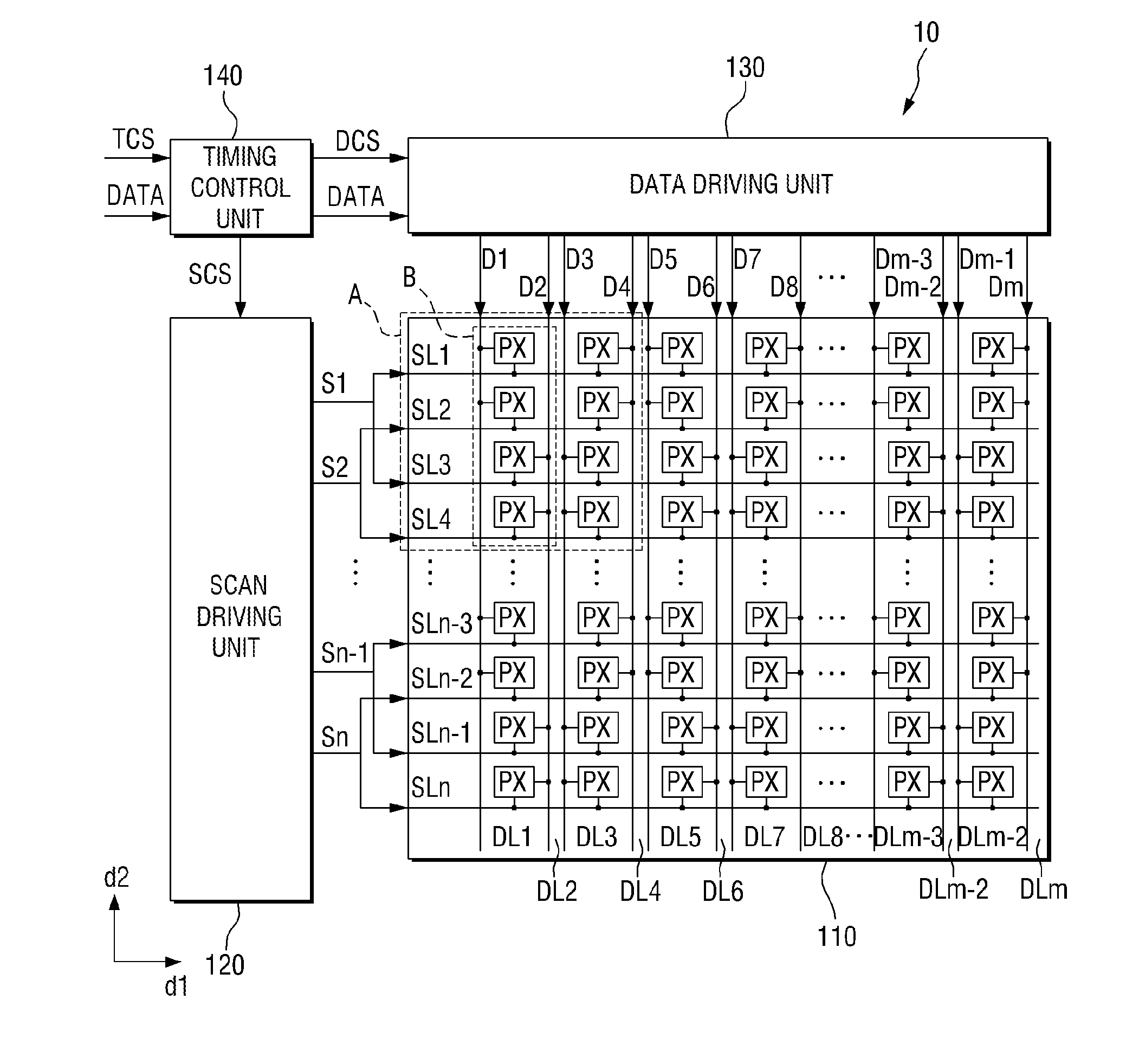
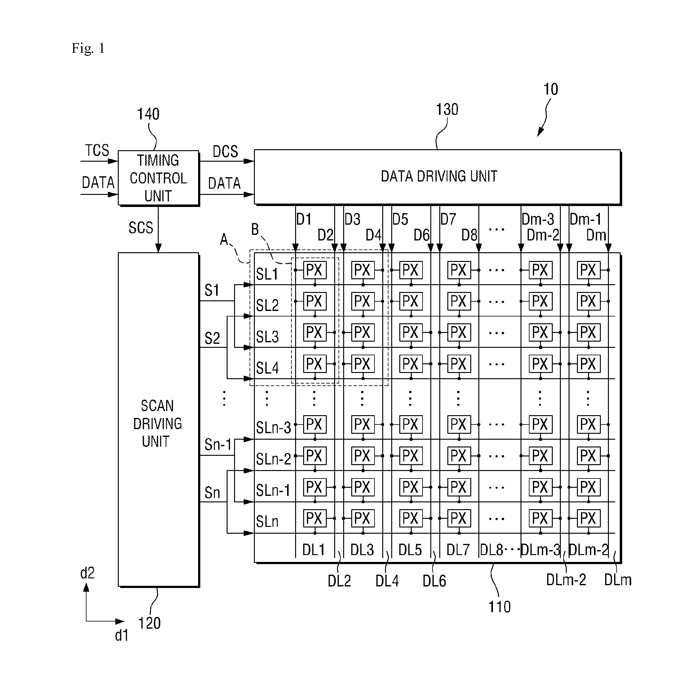
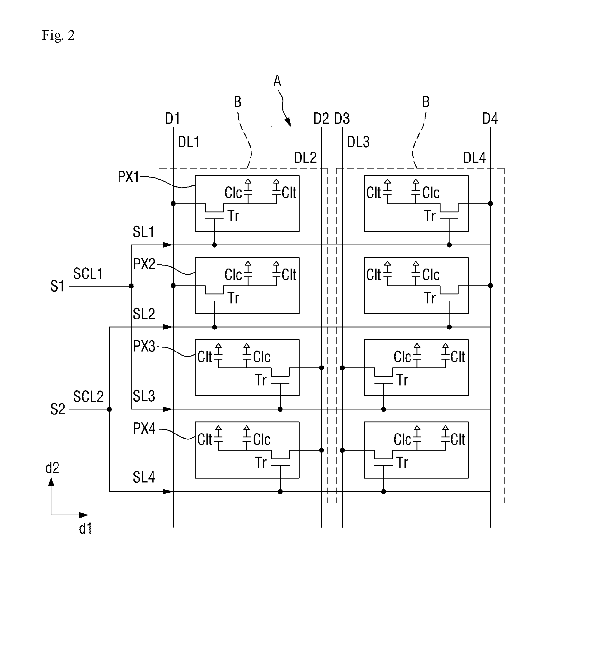
A liquid crystal display device includes a plurality of pixels arranged substantially in a matrix form, where a part of the plurality of pixels defines a pixel column block, a first scan signal is simultaneously applied to an n-th row pixel and an (n+2)-th row pixel of the pixel column block, a second scan signal, which is applied prior to the first scan signal, is simultaneously applied to an (n+1)-th row pixel and an (n+3)-th row pixel of the pixel column block, a first data voltage is applied to the n-th row pixel and the (n+1)-th row pixel, a second data voltage having a polarity different from a polarity of the first data voltage is applied to the (n+2)-th row pixel and the (n+3)-th row pixel, and the polarities of the first data voltage and the second data voltage are inverted on a frame-by-frame basis.

Description

[0001]This application claims priority to Korean Patent Application No. 10-2014-0013131, filed on Feb. 5, 2014, and all the benefits accruing therefrom under 35 U.S.C. §119, the content of which in its entirety is herein incorporated by reference.BACKGROUND[0002]1. Field[0003]Exemplary embodiments of the invention relate to a liquid crystal display device and a method for driving the liquid crystal display device.[0004]2. Description of the Prior Art[0005]A liquid crystal display (“LCD”) device has characteristics of relatively small size, light weight and large-scaled screen in comparison to a conventional cathode ray tube (“CRT”), and thus the LCD device has been widely used in recent. The LCD device may display an image using a plurality of unit pixels including thin film transistors and pixel capacitors. The pixel capacitor may include a pixel electrode, a common electrode and liquid crystals provided between the pixel electrode and the common electrode. The LCD device changes a...

Claims


Application Information

Patent Timeline
IPC IPC(8): G09G3/36
CPCG09G3/3659G09G3/3677G09G3/3607G09G3/3614G09G2300/0413G09G2360/144G09G2300/0809G09G2300/0876G09G2320/0233G09G2320/0295G09G2300/0447G09G3/3655G09G2310/0205G09G2320/0209G09G2320/0219
Inventor LEE, SANG IKYOON, YOUNG SOOGOH, JOON CHULHWANG, IN JAEKIM, BYUNG SUNJANG, DAE GWANGHONG, SEOK HA
Owner SAMSUNG DISPLAY CO LTD
Learn More