
Color-changer

Inactive Publication Date: 2015-08-06
ABB (SCHWEIZ) AG
View PDF8 Cites 2 Cited by
  • Summary
  • Abstract
  • Description
  • Claims
  • Application Information

AI Technical Summary

Benefits of technology

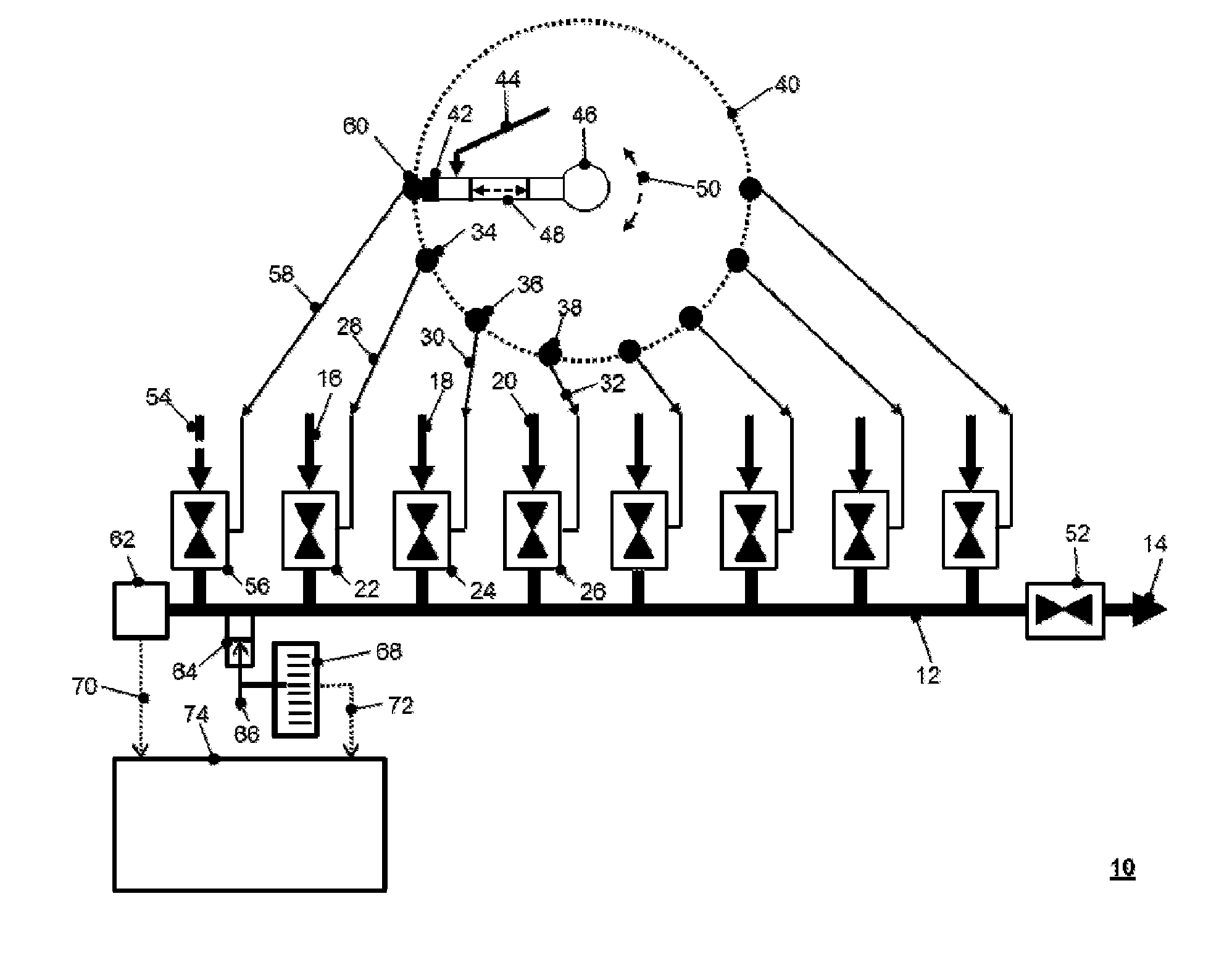
The present patent is about a color changer for painting that has a compact arrangement with a pressure-supply-output and a group of inlets for selecting the desired pressure-line. The pressure-supply-output can move along a linear path for easy selection of the inlet. The color changer also has a second valve-means for hermetically closing all ducts to the output-channel for easy color change. A solvent-supply-channel leads to the output-channel, which can be cleaned by a solvent flowing through it. A pressure sensor can be used to determine a possible pressure-drift within the output-channel, indicating a leakage of one of the valve-means. The color changer is designed to prevent mixed color and leakage of valve-means. The method for detecting a leakage of the valve-means is also provided.

Problems solved by technology

If there is more than exactly one open channel leading to the output-channel, a mixture of different paint materials with different colors will occur and the paint result on the painted object will be unusable.
Even if a control mechanism is provided to prevent a synchronous switching of the valve-means, it is has not been possible to totally exclude the possibility that more than one paint-supply-channel is connected to the output-channel in case of a malfunction of the control-mechanism.
Further, in case there is a leakage in one of the valve-means, a mixture of different paint materials will occur and the paint result will be unusable.
A leakage of a valve-means is rather difficult to detect, in most cases only indirectly by detection of an already unusable paint-result.
Moreover, a correlation of an unusable paint result to a certain atomizer is not always possible, for example, in case an object is painted by different robots having respectively different atomizers.
Thus, a larger time is required to search for the particular defective color-changer.

Method used


Image

  • Color-changer
  • Color-changer

Examples


Embodiment Construction

[0011]Exemplary embodiments of the present disclosure provide a color-changer which, on the one hand, prevents any unintended synchronous switching of the valve-means, and which, on the other hand, permits an easy detection of any leakage of the valve-means (e.g., a valve component including a valve). As used herein, the term “valve-means” is embodied by such a valve component including at least one valve.

[0012]According to an exemplary embodiment of the color-changer, exactly one switchable pressure-supply-outlet is provided which is alternatively connectable with one of the inlets of the pressure-lines, so that at most one of the corresponding valve-means is switchable at the same time.

[0013]Exemplary embodiments of the present disclosure are based on the idea of mechanically excluding synchronous switching of more than one valve-means within the group of valve-means for the paint-supply-lines. By having only one pressure-supply-outlet which can alternately be connected with one o...


PUM


Abstract

A color-changer includes an output-channel having an outlet for paint material, and paint-supply-channels leading to the output-channel. The paint-supply channels are each respectively switchable by a corresponding first valve component. The first valve components are pilotable by a pressured fluid which is conducted through a corresponding pressure-line each having a corresponding inlet. One common, switchable pressure-supply-outlet is alternatively connectable with one of the inlets of the pressure-lines so that at most one of the corresponding first valve components is switchable at the same time. The present disclosure also provides a method for determining the leakage of the first valve component of the color-changer.

Description

RELATED APPLICATIONS[0001]This application claims priority as a continuation of PCT / EP2013 / 002425, which was filed as an International Application on Aug. 13, 2013, and which claims priority to EP 12006408.4, filed on Sep. 12, 2012. The entire contents of these applications are hereby incorporated by reference in their entireties.FIELD[0002]The present disclosure relates to a color-changer.BACKGROUND INFORMATION[0003]It is known that in industrial paint shops—for example, in the automotive industry—a larger number of paint colors are used. Such paint shops may be robot-based and designed for a number of (e.g., 20 to 30) paint colors and a cycle time of 60 s to 90 s per object, for example, to become painted. A color-changer might be mounted on the arm of a robot and is used to change the current paint color being applied. A color changer is a switchable connection in between one paint output—which is the end of an output channel of a color-changer—and a larger number of different pa...

Claims


Application Information

Patent Timeline
IPC IPC(8): B05B12/14G01M3/28B05B12/00B05B15/55
CPCB05B12/006B05B12/1409G01M3/2876B05B15/025B05B12/149B05B15/55
Inventor KROGEDAL, ARNULF
Owner ABB (SCHWEIZ) AG
Learn More