Vertical-type continuous high-speed stirring device

a high-speed stirring, vertical-type technology, applied in the direction of rotary stirring mixers, emulsification, transportation and packaging, etc., can solve the problem that the amount of emulsion generated per minute is not necessarily sufficien

Inactive Publication Date: 2015-08-06
VSD
View PDF0 Cites 11 Cited by
  • Summary
  • Abstract
  • Description
  • Claims
  • Application Information

AI Technical Summary

Benefits of technology

[0021]According to one or more embodiments of the present invention, it is possible to provide a verti

Problems solved by technology

In the case of the above-described conventional emulsion production device, however, an amount of emulsion g

Method used


Image

  • Vertical-type continuous high-speed stirring device
  • Vertical-type continuous high-speed stirring device
  • Vertical-type continuous high-speed stirring device

Examples


Embodiment Construction

[0026]Hereinafter, an embodiment of a vertical-type continuous high-speed stirring device according to the present invention will be described with reference to the accompanying drawings.

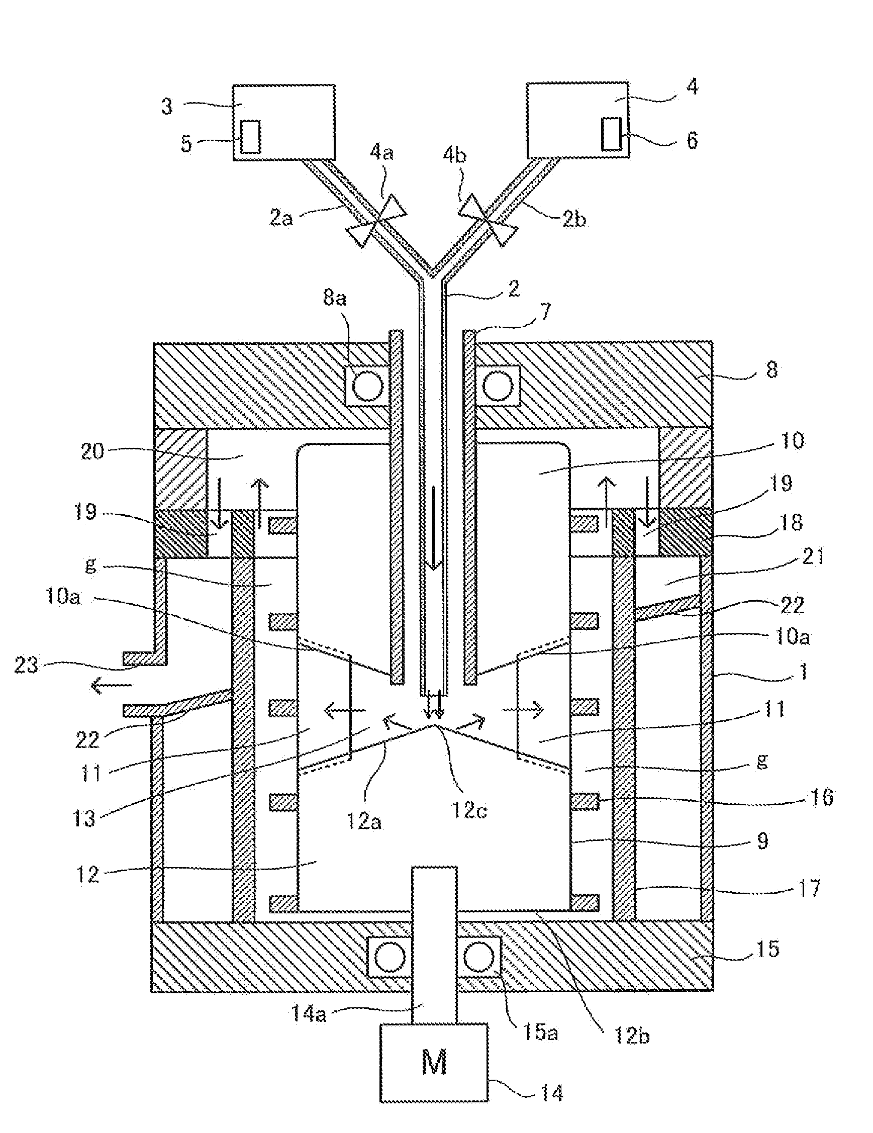
[0027]FIG. 1 is a cross-sectional view showing an embodiment of the vertical-type continuous high-speed stirring device according to an embodiment of the present invention.

[0028]As shown in FIG. 1, as for the basic configuration of the high-speed stirring device, a liquid supply pipe 2 is provided in a vertical direction along a central axis of a cylindrical container 1 to mix and transport oil (light oil, kerosene, Bunker A, or the like) and water. The liquid supply pipe 2 includes branch pipes 2a and 2b, which diverge from an upper portion thereof in a way that makes a Y-shape. To the branch pipes 2a and 2b, an oil tank 3 and a water tank 4 are respectively connected. Specifically, the liquid supply pipe 2 is made of stainless steel, with the Y-shaped, two-pronged upper portion having the branch p...


PUM

PropertyMeasurementUnit
Speedaaaaaaaaaa
Gravityaaaaaaaaaa
Circumferenceaaaaaaaaaa

Abstract

A stirring device is provided including a liquid supply pipe disposed on a central axis of a cylindrical container and discharges liquid into the cylindrical container; a rotation hollow shaft disposed coaxially outside the liquid supply pipe; a rotor which is coaxially fixed to the rotation hollow shaft including a plurality of rotor blades; a screw conveyor plate wound around the rotor in a spiral pattern; an inner-side cylindrical container provided in the cylindrical container around the rotor; a division plate which defines an upper and a lower portion inside the cylindrical container having a plurality of through-holes; an inclined bottom plate disposed between the cylindrical container below the division plate and the inner-side cylindrical container; a processed fluid outlet provided on a side wall of the cylindrical container; and a motor to rotate the rotation hollow shaft.

Description

RELATED APPLICATIONS[0001]This application claims priority to Japanese Application No. 2013-069682, filed Mar. 28, 2013, and to PCT / JP2013 / 005761, filed Sep. 27, 2013, which also claims priority to Japanese Application No. 2013-069682, each of whose contents are expressly incorporated by reference herein.TECHNICAL FIELD[0002]One or more aspects of the present invention relate to a device that stirs a liquid that is mixed with at least one type of liquid or powder mixed liquid, and particularly to a vertical-type continuous high-speed stirring device that is equipped with a rotor blade that is rotated at high speed by a vertical rotation shaft.BACKGROUND ART[0003]What is known is emulsion fuel that is made by adding water to fuel oil such as light oil, heavy oil, or heavy gravity oil and stirring, and dispersing the water in the fuel oil. The heavy gravity oil is an oil that is poor in liquidity at normal temperature and becomes liquid only when heated to high temperatures; the heavy...

Claims


Application Information

Patent Timeline
IPC IPC(8): B01F7/24B01F15/02B01F7/18B01F7/00B01F7/16B01F23/47
CPCB01F7/00708B01F7/169B01F7/18B01F7/247B01F15/0276B01F2215/0481B01F7/007B01F7/243B01F3/0807B01F3/0857F23K5/12B01F23/431B01F23/41B01F27/2122B01F27/9211B01F23/47B01F27/80B01F27/9214B01F27/87B01F27/90B01F27/2123B01F35/75415
Inventor KUROSAWA, KEIJI
Owner VSD
Why Eureka
Try Eureka