
Gear-driven generator with offset axis of rotation and integrated cooling system

a generator and offset axis technology, applied in the direction of dynamo-electric machines, mechanical energy handling, magnetic circuit shape/form/construction, etc., can solve the problems of limited pad space around, unique weight and size limitation challenges for generator designers, and inability to provide the required level of cooling in the pad area

Inactive Publication Date: 2015-07-30
OECO
View PDF8 Cites 56 Cited by
  • Summary
  • Abstract
  • Description
  • Claims
  • Application Information

AI Technical Summary

Benefits of technology

The present invention is an electrical generator that includes a self-contained step-up gearbox to increase its rotational speed, while still keeping the required space and weight minimal. The generator also includes a spur gear mesh assembly and mating drive shaft assembly that allows for an offset axis of rotation, making it possible to occupy non-co-axial space near the engine. Additionally, the generator has a self-contained fluid cooling and lubrication system that uses on-board fuel to absorb generated heat and lubricate generator components. The technical effects of this invention include increased efficiency, reduced size, and weight of the generator, as well as improved cooling and lubrication of its components.

Problems solved by technology

It is appreciated that the generation of electrical power on an aircraft can present unique weight and size limitation challenges for the generator designer.
Additionally, the pad may have limited space around it in which to locate the generator.
Still further, the ability to provide the required level of cooling in the pad area may be impaired because the air flow is unpredictable.
Furthermore, none of the known electrical generators include the features of the various generator embodiments described herein in combination with the innovative self-contained fuel / oil heat exchanger used to cool the various generator embodiments described.

Method used


Image

  • Gear-driven generator with offset axis of rotation and integrated cooling system
  • Gear-driven generator with offset axis of rotation and integrated cooling system
  • Gear-driven generator with offset axis of rotation and integrated cooling system

Examples


Embodiment Construction

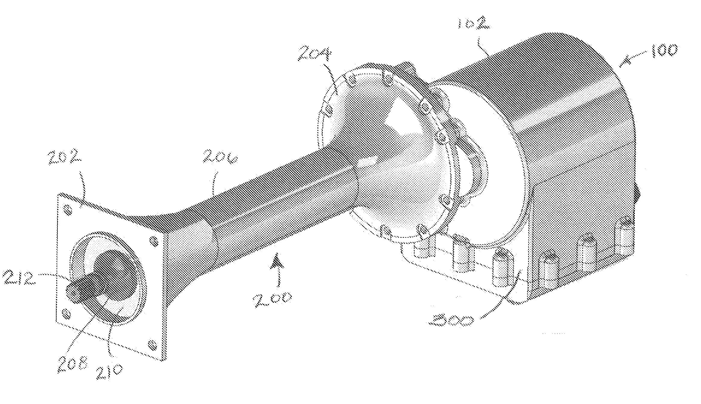
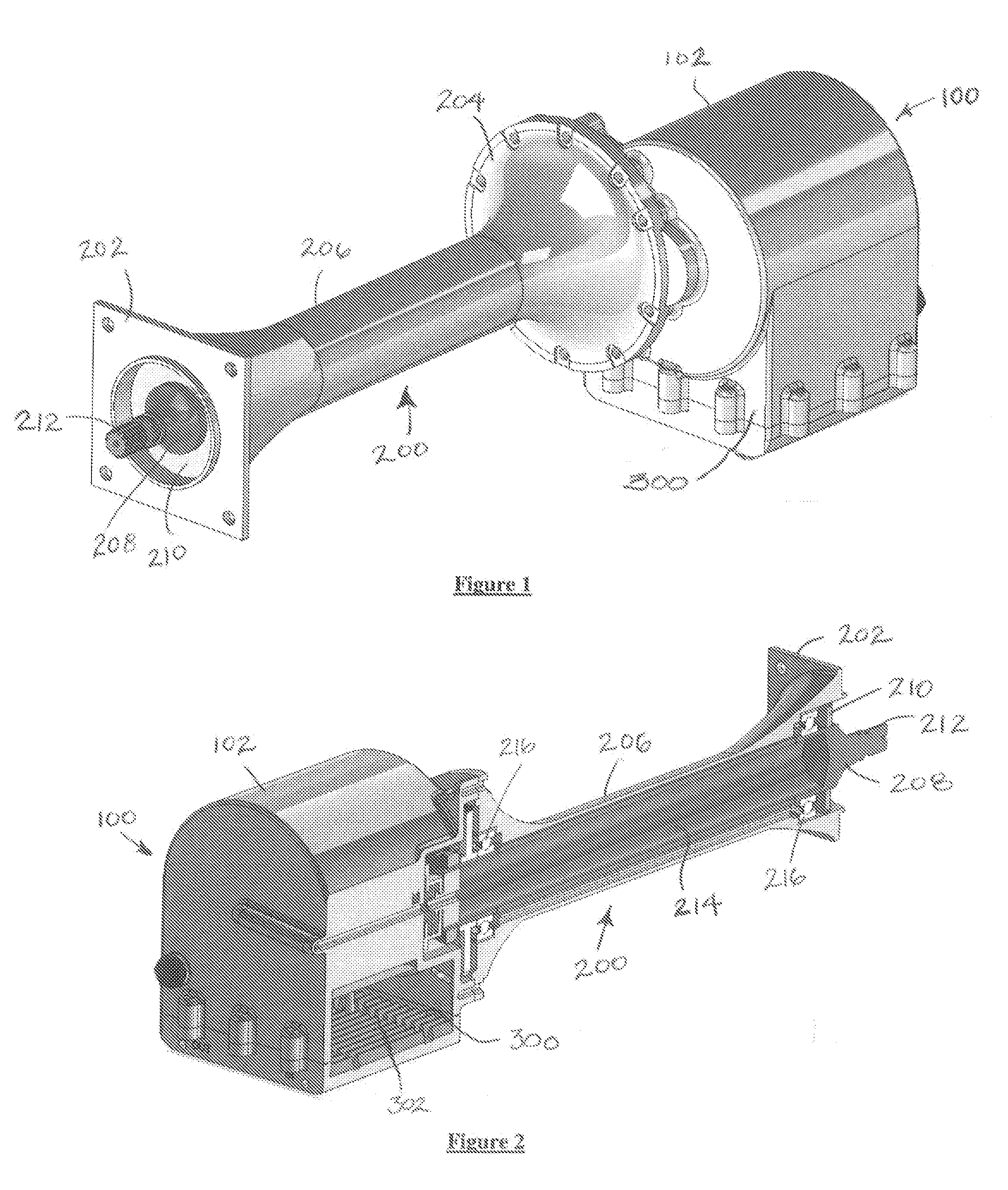
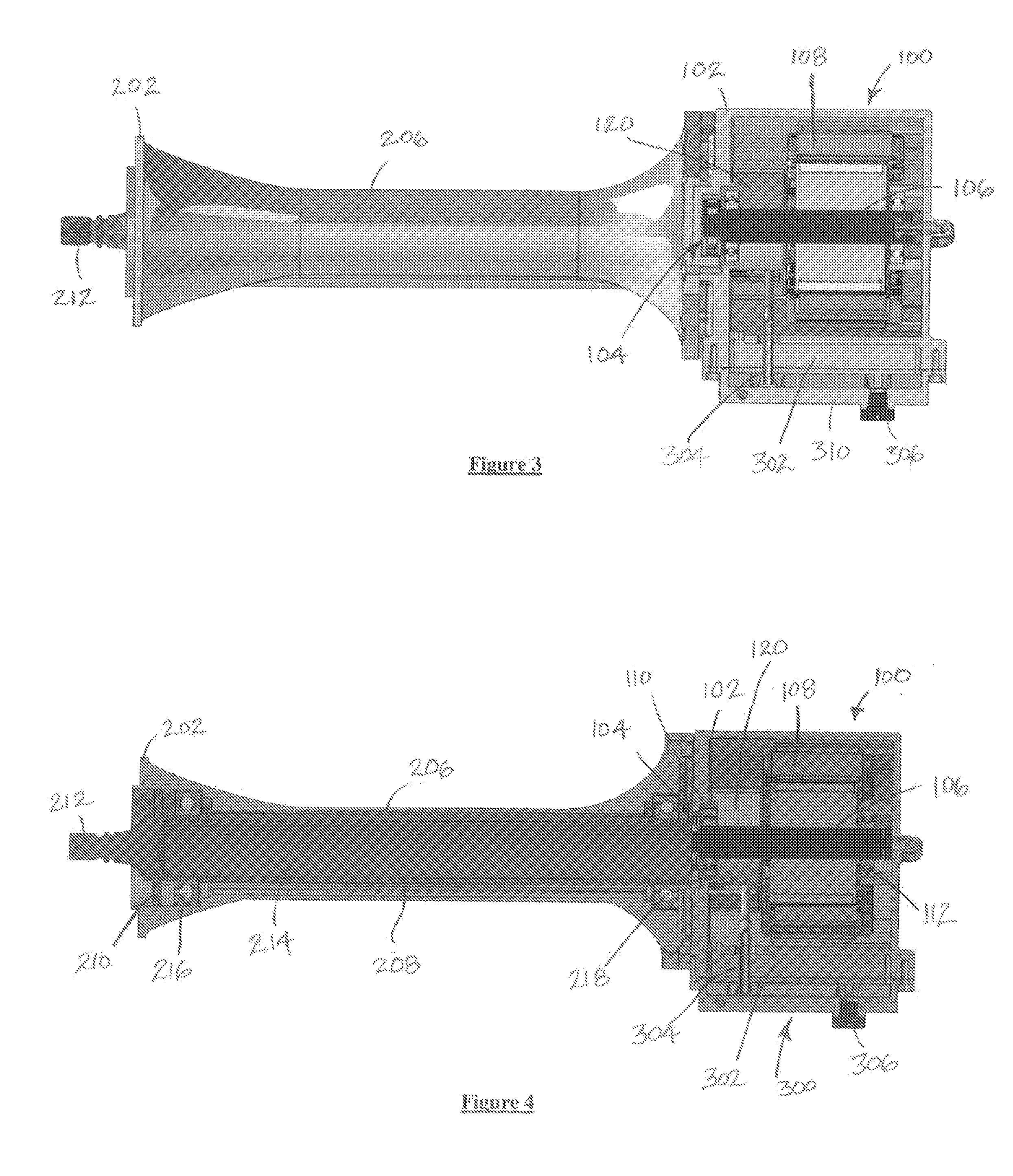
[0019]Reference will now be made in detail to a preferred embodiment of the present invention, an example of which is illustrated in the accompanying drawings. With reference to FIGS. 1 and 2, a relatively a high speed electrical generator assembly 100 may be driven by a comparatively low speed drive shaft assembly 200 and optionally cooled and lubricated with a built-in heat exchanger assembly 300. The heat exchanger assembly 300 may absorb and transfer waste heat generated by the electrical generator assembly 100 to a cooling area (not shown) with circulating fuel or some other fluid or medium.

[0020]The electrical generator assembly 100 may include a generator housing 102 in which the generator assembly components are sealed. The heat exchanger assembly 300 may include a hollow reservoir 302 for the receipt of coolant or oil.

[0021]The drive shaft assembly 200 may have a first end at which a drive pad interface 202 is provided and a second end having a generator interface housing 2...


PUM


Abstract

An electrical generator and drive shaft assembly are disclosed. The electrical generator may include a step-up gearbox to minimize the required volume and weight of the generator for onboard aircraft electricity generation. The electrical generator and drive shaft interface may be axially offset. The electrical generator may also include a self-contained fluid cooling and lubrication system that may employ on-board fuel to absorb generated heat and / or oil to lubricate and cool generator components.

Description

CROSS REFERENCE TO RELATED APPLICATIONS[0001]This application relates to, and claims the benefit of the earlier filing date and priority of U.S. Provisional Patent Application No. 61 / 920,204, filed on Dec. 23, 2013, entitled “Gear-Driven Generator with Offset Axis of Rotation and Integrated Cooling System.”FIELD OF THE INVENTION[0002]The present invention relates to electrical generators and systems and methods for cooling electrical generators.BACKGROUND[0003]Electrical generators, including geared generators, have existed for a while and have been developed for a variety of conditions and applications. One application for which electrical generators are needed is to provide on-board electrical power for vehicles, such as aircraft, although the invention should not be limited to these applications. It is appreciated that the generation of electrical power on an aircraft can present unique weight and size limitation challenges for the generator designer.[0004]For example, a typical ...

Claims


Application Information

Patent Timeline
IPC IPC(8): H02K9/19H02K7/116
CPCH02K7/116H02K9/19H02K1/16H02K7/1807
Inventor RAAD, BERNARD ANTHONY
Owner OECO
Learn More