
Control system capable of changing the state of an electrical appliance according to exceptional conditions

Inactive Publication Date: 2015-07-30
D-LINK
View PDF6 Cites 6 Cited by
  • Summary
  • Abstract
  • Description
  • Claims
  • Application Information

AI Technical Summary

Benefits of technology

The present invention is a control system that can change the state of electrical appliances based on exceptional conditions. The control system includes a plurality of switch devices and a processing server. The switch devices are electrically connected to the electrical appliances and can turn on or off them. The processing server stores a first schedule of first electrical appliance data and first time data, which includes turn-on and turn-off times for each switch device. When an exceptional condition occurs, the processing server sends a message to the corresponding switch device and adjusts its state accordingly. This system provides more user-friendliness and flexibility in controlling the electrical appliances.

Problems solved by technology

And with the prevalence of such electrical appliances, household electricity consumption has risen year by year.
Nevertheless, the “intelligent electricity management services” lack flexibility in practical use.
Taking the alert messages for example, although the user can know, by the alert function of a mobile device, the electrical appliances that need unplugging, it is necessary for the user to unplug each of those appliances by hand, which is extremely inconvenient.
As to the central control system, although its automatic control over each electrical appliance seems to greatly simply the user's actions, the fact that the user's daily schedules may vary (e.g., work days vs. holidays) and may be interrupted by exceptional events (e.g., a dinner gathering at short notice that delays the user's coming home) requires the user to input the exceptional items into the central control system according to the differences in his or her daily schedules, which is also inconvenient.

Method used


Image

  • Control system capable of changing the state of an electrical appliance according to exceptional conditions
  • Control system capable of changing the state of an electrical appliance according to exceptional conditions
  • Control system capable of changing the state of an electrical appliance according to exceptional conditions

Examples


Embodiment Construction

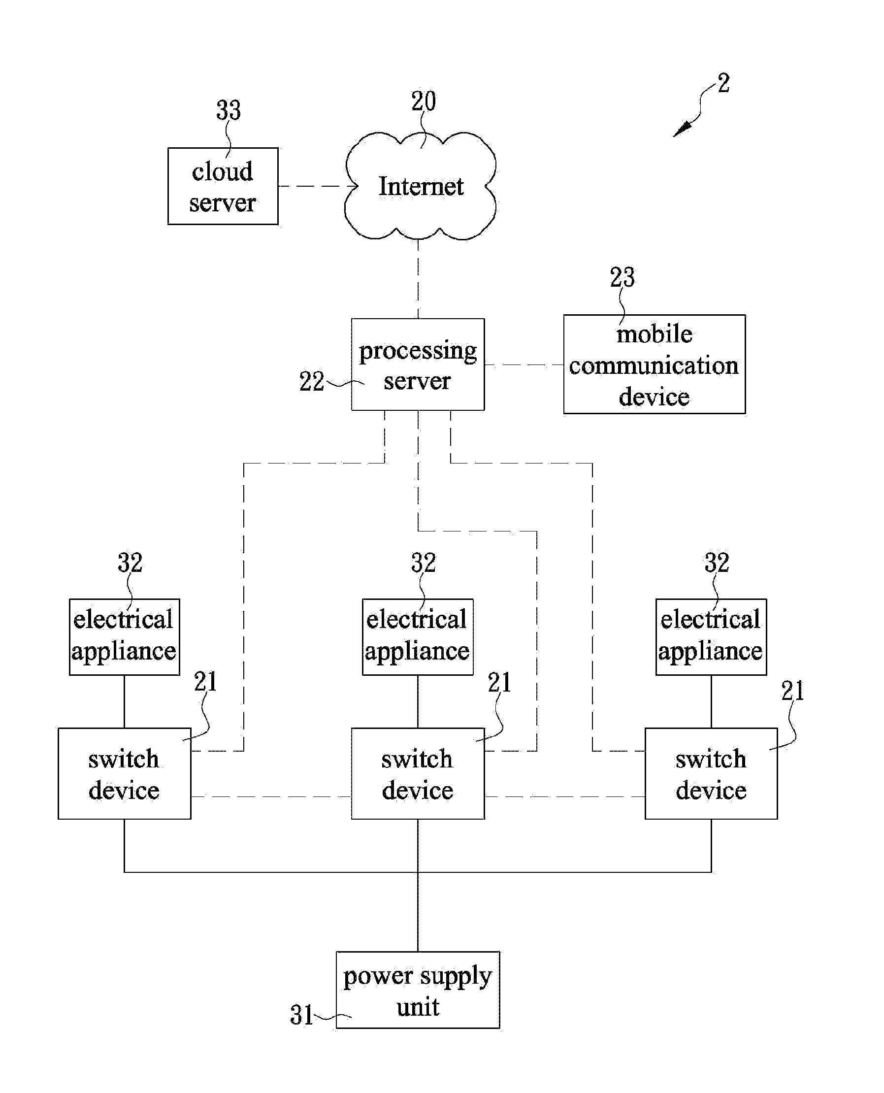
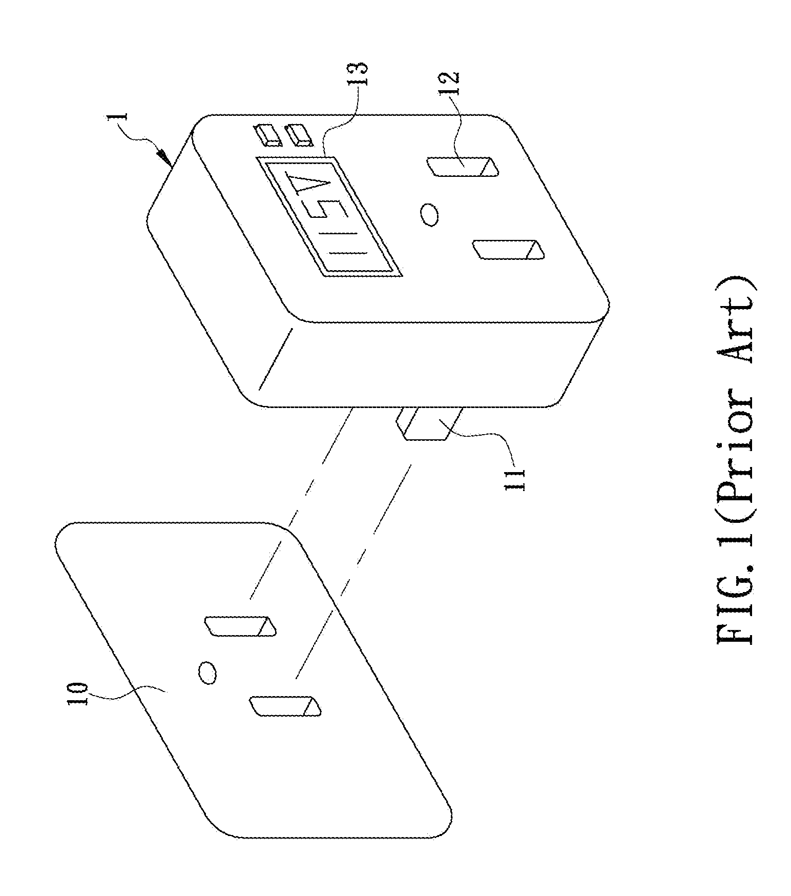
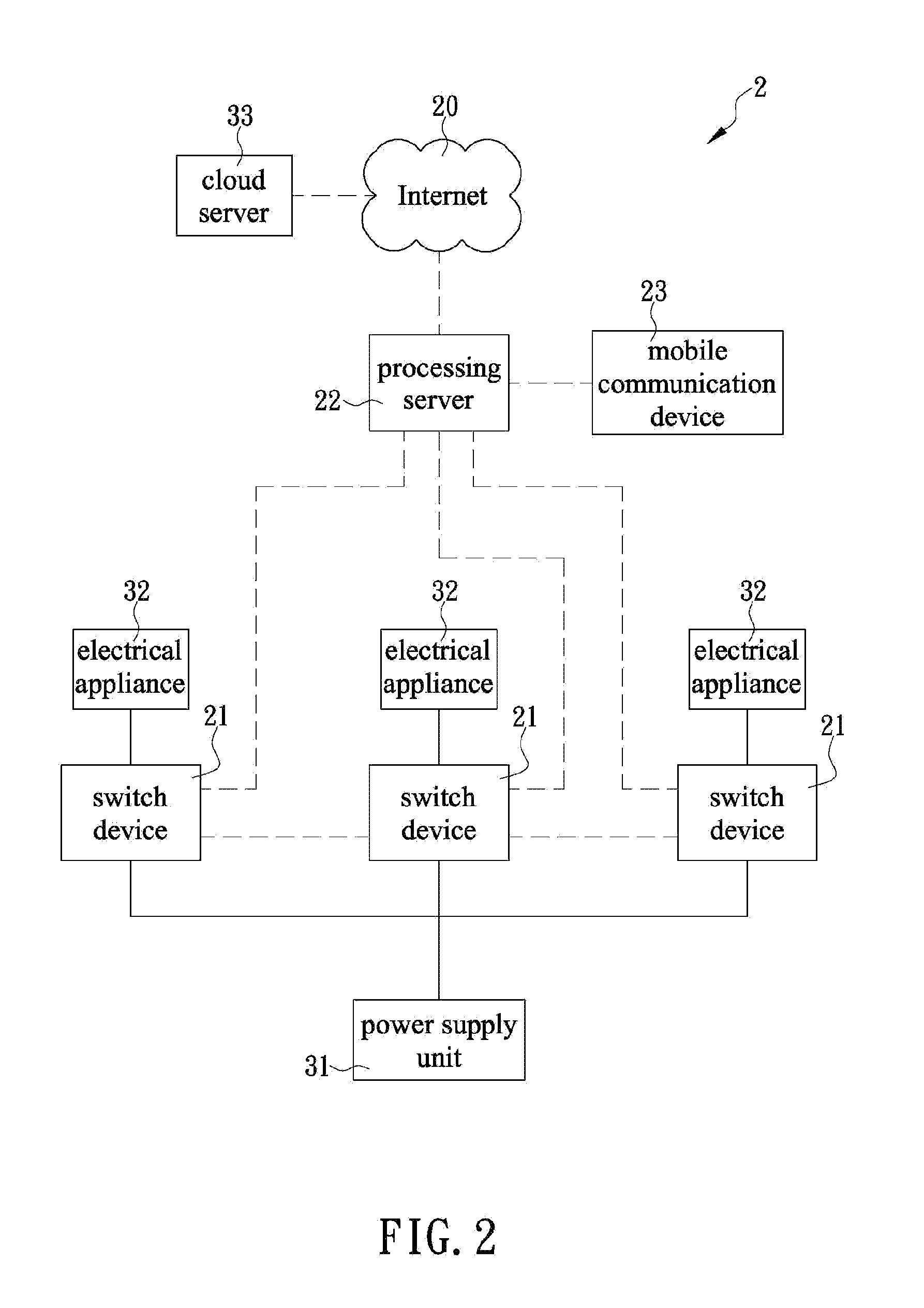
[0018]The present invention discloses a control system capable of changing the state of an electrical appliance according to exceptional conditions. Referring to FIG. 2 for the first preferred embodiment of the present invention, the control system 2 includes a plurality of switch devices 21 and a processing server 22. In this embodiment, the switch devices 21 are intelligent power sockets similar in appearance to the electricity management device 1 shown in FIG. 1 (with the display screen 13 being a non-essential component) and can each be connected to a power supply socket in order to receive the electricity delivered from a power supply unit 31. Each switch device 21 can be connected with an electrical appliance 32 and serve as a bridge between the electrical appliance 32 and the power supply unit 31. It should be pointed out that the switch devices 21 are not limited in form to sockets; each switch device 21 may alternatively be a power supply component in an electrical applianc...


PUM


Abstract

The present invention is to provide a control system, which includes a plurality of switch devices each electrically connected between an electrical appliance and a power supply unit for turning on or off the electrical appliance, and a processing server respectively connected to the switch devices and capable of turning the switch device into a turned-on or turn-off state at a predetermined time according to a time schedule stored therein. In addition, the processing server can generate an exception time data when determining an exceptional condition (e.g., a specific event took place, a user did not leave home on time, or the user turned on the electrical appliance on his or her own initiative) occurs, and then change the state of each switch device preferentially according to the exception time data, so as to adjust the time schedule in a timely manner upon determining the occurrences of different exceptional conditions.

Description

FIELD OF THE INVENTION[0001]The present invention relates to a control system, more particularly to a control system which includes a plurality of switch devices each electrically connected to an electrical appliance and capable of turning on or off the electrical appliance, and a processing server respectively connected to the switch devices and capable of turning the switch device into a turned-on or turn-off state at a predetermined time according to time schedule stored therein, wherein the processing server can generate an exception time data when determining an exceptional condition (e.g., a specific event took place, a user did not leave home on time, or the user turned on the electrical appliance on his or her own initiative) occurs, and then change the state of each switch device preferentially according to the exception time data, so as to adjust the time schedule in a timely manner upon determining the occurrences of different exceptional conditions.BACKGROUND OF THE INVE...

Claims


Application Information

Patent Timeline
IPC IPC(8): G05F1/66G05B15/02
CPCG05B15/02G05F1/66G05B2219/2639G06F1/329Y02D10/00
Inventor HSU, WEI-CHUNGLIU, MING-HANHUANG, JUN-HAOCHEN, JIA-JUN
Owner D-LINK
Learn More