
Sheet feeding apparatus and image forming apparatus

a feeding apparatus and a technology of forming apparatus, applied in the direction of transportation and packaging, thin material processing, article separation, etc., can solve the problems of reducing separation performance and more strictly managing the position accuracy of the return roller, so as to prevent the overlapping of sheets

Inactive Publication Date: 2015-07-30
CANON KK
View PDF11 Cites 3 Cited by
  • Summary
  • Abstract
  • Description
  • Claims
  • Application Information

AI Technical Summary

Benefits of technology

The invention is a sheet feeding system that can separate and feed sheets reliably, without damaging them or relying on the position accuracy of the rotating member. This system can be used in an image forming apparatus. The technical effect of this invention is that it allows for more efficient and reliable sheet feeding in an image forming apparatus, which can improve overall performance and reliability.

Problems solved by technology

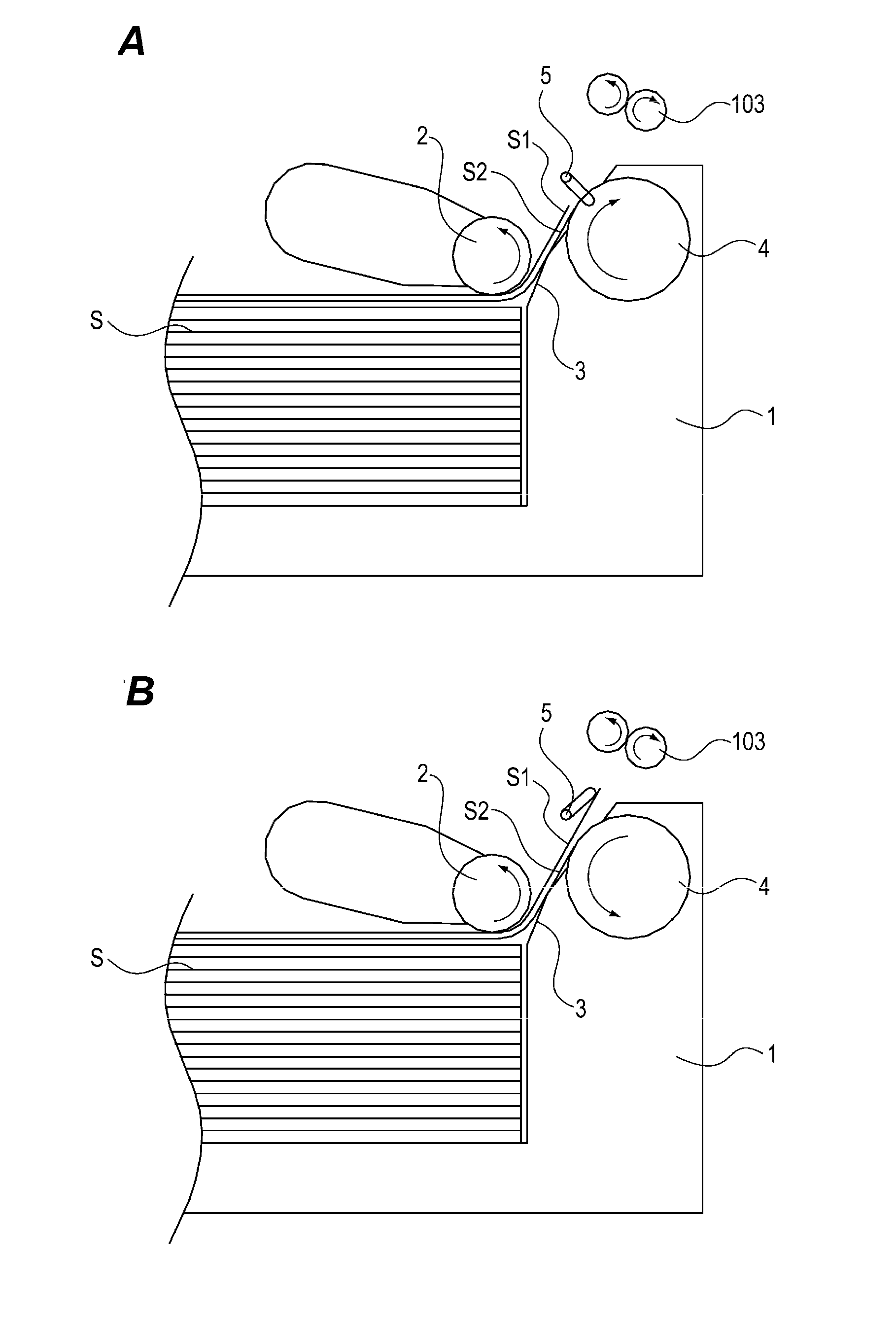
However, as described above, in a method of separating the sheets using the separation slope surface portion and the return roller, when a protruding amount of the return roller 4 toward the sheet feeding path side is set to be small as illustrated in FIG. 9C, separation performance is degraded and there has been a case where the overlapping occurs.
In addition, since an optimal protruding amount at the return roller position toward the feeding path side is different depending on the rigidity or the thickness of the sheet, there has been a problem of having to more strictly manage the position accuracy of the return roller.

Method used


Image

  • Sheet feeding apparatus and image forming apparatus
  • Sheet feeding apparatus and image forming apparatus
  • Sheet feeding apparatus and image forming apparatus

Examples


first embodiment

Image Forming Apparatus

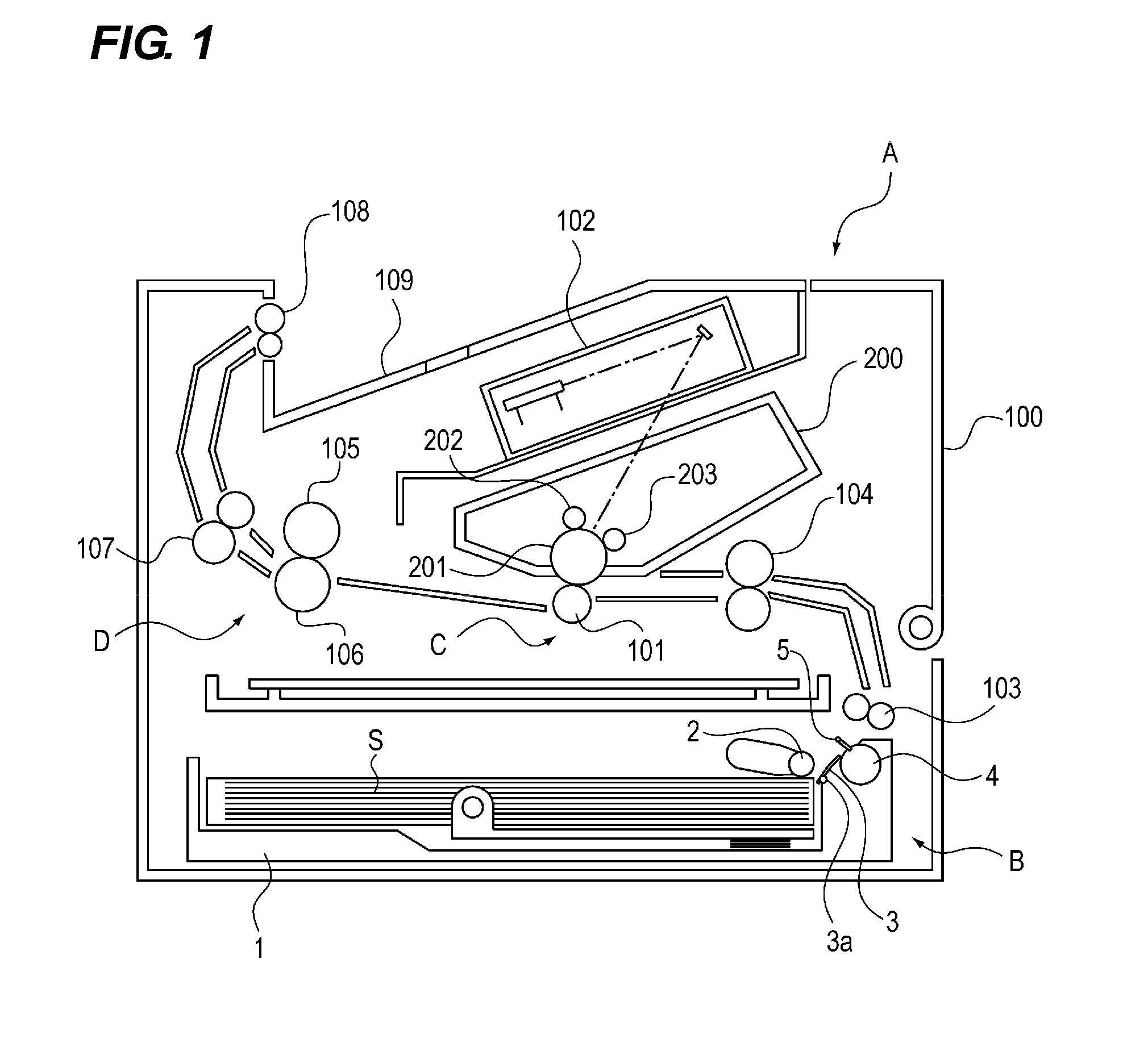
[0023]An entire configuration of an image forming apparatus which includes a sheet feeding apparatus according to a first embodiment of the present invention will be described with reference to FIG. 1.

[0024]FIG. 1 is a schematic cross-sectional view of the image forming apparatus. An image forming apparatus A includes, when it is roughly divided, a sheet feeding apparatus B which feeds a sheet S from a stacking portion, and an image forming portion which forms a toner image on the fed sheet S. Then, the image forming portion includes an image transfer portion C which transfers the toner image onto the sheet and a fixing device D which fixes the toner image to the sheet.

[0025]The image transfer portion C includes a cartridge 200 which is detachably attachable to an image forming apparatus body 100, a transfer roller 101, and a laser scanner unit 102. The cartridge 200 includes a photosensitive drum 201, a charging device 202, and a development device 203.

[0026]...

second embodiment

[0045]Next, an apparatus according to a second embodiment will be described with reference to FIGS. 6A and 6B. Note that, since the basic configurations of the apparatus in the present embodiment are same as those of the above-described embodiment, the redundant descriptions will be omitted, and the members having the same functions as those of the above-described embodiment will be denoted by the same reference numerals.

[0046]A surface of a return roller 4 is made of a rubber material having a relatively high frictional resistance. For this reason, when a leading end of a sheet fed by a feeding roller 2 butts against the return roller 4 rotating in a direction to return the sheet, there is a possibility that the folding of the leading end of the sheet, and the like occur (see FIG. 9D).

[0047]Thus, in the present embodiment, there is provided a rotation switching mechanism which switches a rotation direction of the return roller 4. Then, the return roller 4 is rotated in a direction ...


PUM


Abstract

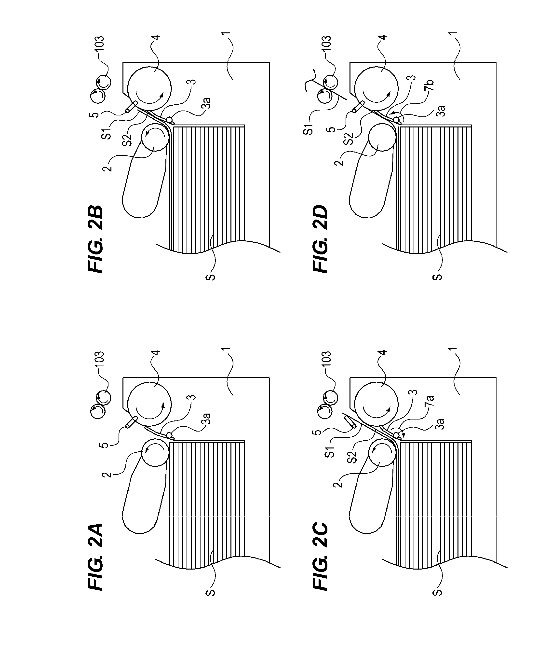
A sheet feeding apparatus includes: a stacking portion on which a sheet is stacked; a sheet feeding portion configured to feed the sheet stacked on the stacking portion; a rotating member provided on a downstream side of the stacking portion in a feeding direction of the sheet and rotates in a direction opposite to the feeding direction; a slope portion of which at least a part is provided on the downstream side of the stacking portion in the feeding direction and on an upstream side of the rotating member, and which is inclining so that the downstream side in the feeding direction become an upper side; and a changing unit configured to change a protruding amount of the rotating member toward a sheet feeding path of the sheet.

Description

BACKGROUND OF THE INVENTION[0001]1. Field of the Invention[0002]The present invention relates to a sheet feeding apparatus which separates stacked sheets one by one and feeds a sheet, and an image forming apparatus which includes the sheet feeding apparatus.[0003]2. Description of the Related Art[0004]In an image forming apparatus, there is provided a sheet feeding apparatus which separates sheets one by one and feeds a sheet to an image forming portion. In such a sheet feeding apparatus, a slope surface portion may be used as a method of separating the sheets one by one. In the apparatus, as illustrated in FIG. 9A, a sheet S stacked on a stacking portion 1 is conveyed by a feeding roller 2, the sheet is caused to butt against the slope surface portion of a separation member 3 on the downstream side of the feeding roller 2, and only one uppermost sheet is separated by a resistance force at that time and fed (U.S. Pat. No. 8,322,707).[0005]Note that, in order to reliably separate ove...

Claims


Application Information

Patent Timeline
Patent Type & Authority Applications(United States)
IPC IPC(8): B65H7/02B65H5/26B65H3/02B65H5/06
CPCB65H7/02B65H3/02B65H5/26B65H5/06B65H3/5261B65H3/56B65H3/66B65H2511/214B65H2701/1311B65H2701/1313B65H2220/01B65H2220/02B65H2220/11
Inventor TANAKA, NORIAKI
Owner CANON KK
Learn More