Eureka AIR delivers breakthrough ideas for toughest innovation challenges, trusted by R&D personnel around the world.

Atomizer

a technology of atomizer and atomizer, which is applied in the direction of tobacco, lighting and heating apparatus, heating types, etc., can solve the problems of high material cost, troublesome user arrangement or hiding of wire and pipe, and inability to adjust for users

Inactive Publication Date: 2015-07-30
TSAI WEI LI
View PDF23 Cites 94 Cited by
  • Summary
  • Abstract
  • Description
  • Claims
  • Application Information

AI Technical Summary

Benefits of technology

The present invention provides an atomizer with adjustable length between the main unit and the vaporizer, without conducting wire between them. The atomizer is remote controllable, meaning it can be controlled from a distance using a remote controller. The main circuit includes a start switch, inflator pump, and battery, while the vaporizer includes a control circuit, battery, pneumatic switch, heater, and cartridge. The main unit has a case and a cap, with the start switch being triggered by pressing the cap. The vaporizer also has a handle shell and cartridge shell for easy connection. The main circuit and remote control circuit can pair using a button, and they both have LED displays for status. The pipe has joint holes and pins for easy connection, and the main circuit can be powered off using a function switch. The remote controller has a case and cap for easy assembly, and it also has springs to support the cap. The main circuit also has a power socket for charging the battery. Overall, the present invention provides an improved atomizer with improved functionality and user experience.

Problems solved by technology

In the limitation of the prior art, the length of the pipe and the conducting wire between the main unit and the vaporizer of the atomizer is determined when the product is produced.
It is not adjustable for users.
For long conducting wire and pipe, the cost of material is high.
It is troublesome for user to arrange or hide the wire and pipe when using the atomizer.
For short conducting wire and pipe, the configuration for locating the main unit and the vaporizer is limited.
The patterns of application and performance are limited.

Method used


Image

  • Atomizer
  • Atomizer
  • Atomizer

Examples


Embodiment Construction

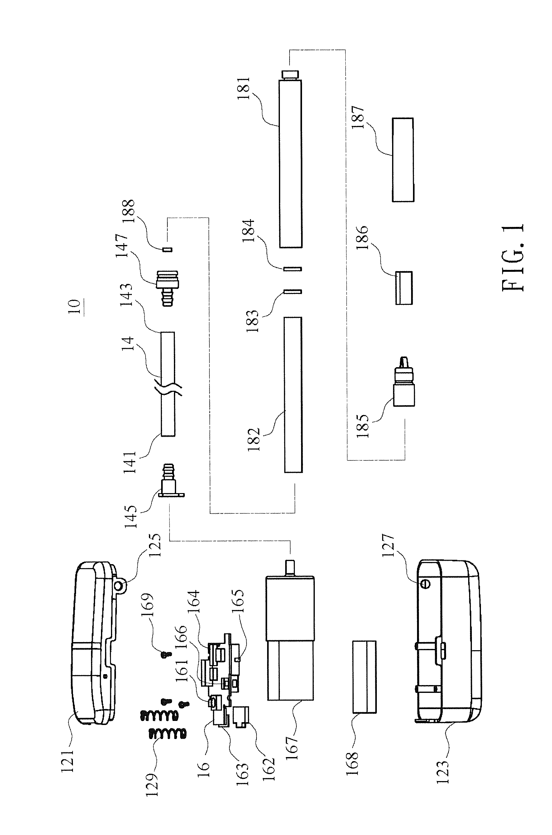
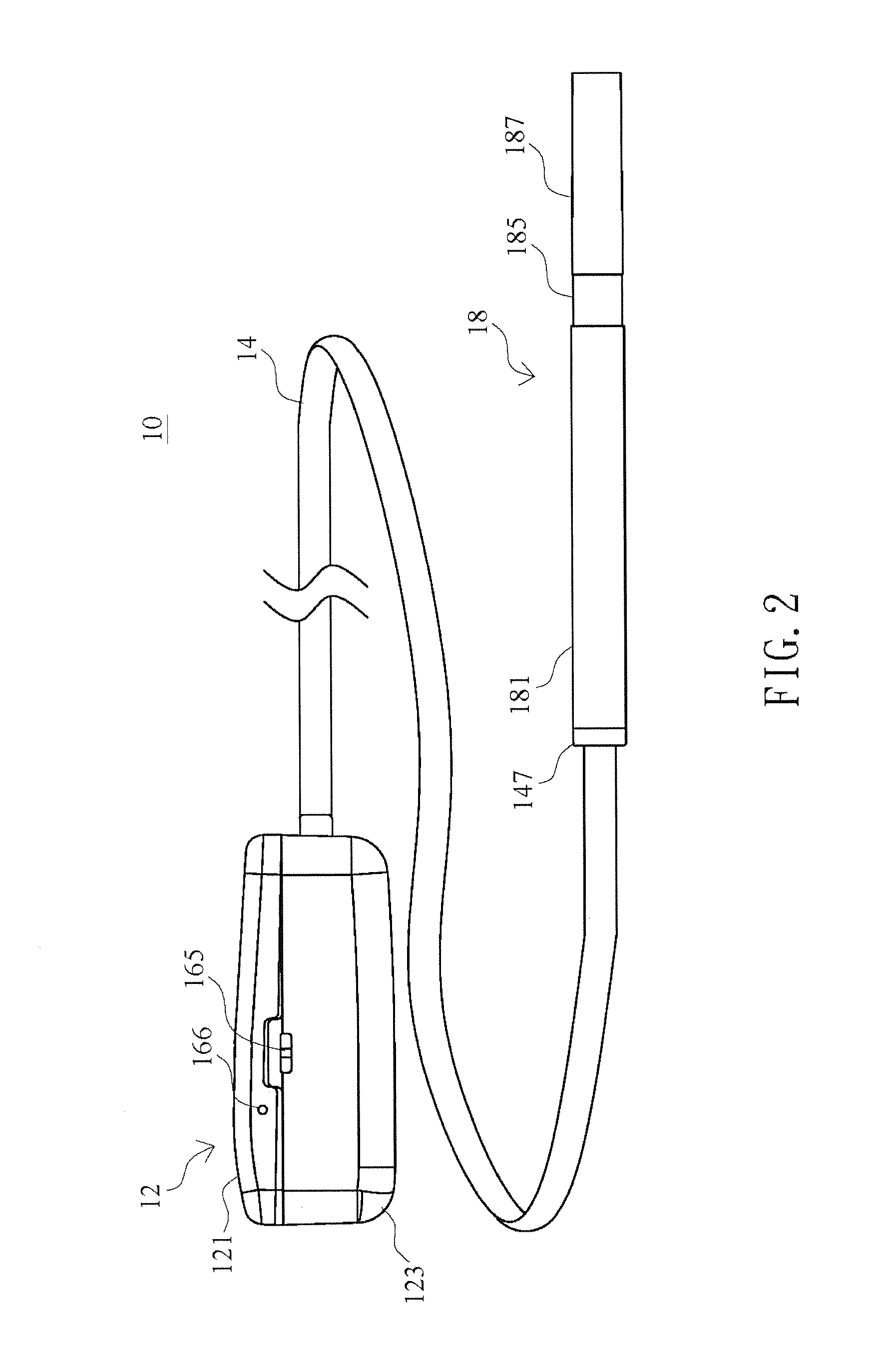
[0032]Referring to FIG. 1 and FIG. 2, a schematic explosion diagram and a schematic assembly diagram of the atomizer in accordance with one embodiment of the present invention are illustrated. In the present embodiment, the atomizer 10 comprises a main unit 12, a pipe 14 and a vaporizer 18. The main unit 12 comprises a main circuit 16, a battery 168, and an inflator pump 167. The pipe 14 having a first end 141 and a second end 143. The first end 141 and the second end 143 of the pipe 14 are connected to the inflator pump 167 and the vaporizer 18 respectively. The vaporizer 18 comprises a battery 182, a control circuit 183, a pneumatic switch 184, a heater 185, and a cartridge 186.

[0033]A start switch 161 is disposed in the main circuit 16. When a user triggers the start switch 161, the main circuit 16 drives the inflator pump 167 to work and produce airflow. The airflow is transmitted to the vaporizer 18 through the pipe 14 and triggers the pneumatic switch 184. The control circuit ...


PUM


Abstract

An atomizer is disclosed. The atomizer of the present invention comprises a main unit, a pipe, and a vaporizer. The vaporizer of the present invention comprises a pneumatic switch which is triggered by the airflow from the main unit. There is no conducting wire between the main unit and the vaporizer. The length of the pipe is determined according to the requirement of the user. In one embodiment of the present invention, the atomizer is remote controllable.

Description

FIELD OF THE INVENTION[0001]The present invention relates to an atomizer, and more particularly to an atomizer wherein the length of the pipe between the main unit and the vaporizer is adjustable.BACKGROUND OF THE INVENTION[0002]Nowadays, the atomizer of the prior art comprises a conducting wire between the main unit and the vaporizer for power and control signal transmission. In the limitation of the prior art, the length of the pipe and the conducting wire between the main unit and the vaporizer of the atomizer is determined when the product is produced. It is not adjustable for users.[0003]For long conducting wire and pipe, the cost of material is high. It is troublesome for user to arrange or hide the wire and pipe when using the atomizer. For short conducting wire and pipe, the configuration for locating the main unit and the vaporizer is limited. Furthermore, due to the user's habit and physique, different length of the wire and pipe is needed.[0004]In the prior art, the atomi...

Claims


Application Information

Patent Timeline
IPC IPC(8): A24F47/00H05B1/02A24F40/10A24F40/48A24F40/485A24F40/50A24F40/60A24F40/65
CPCH05B1/0244A24F47/008A24F40/60A24F40/10A24F40/485A24F40/65A24F40/50A24F40/48
Inventor TSAI, WEI LI
Owner TSAI WEI LI
Why Eureka
Eureka Blog
Learn More