
Plumbing Control System With Distress Signal

a technology of distress signal and control system, applied in the direction of fluid pressure measurement, process and machine control, instruments, etc., can solve the problems of inmate safety, time-consuming, difficult, and expensive retrofitting of existing buildings and facilities, and achieve the effect of reducing the risk of inmate harm

Active Publication Date: 2015-07-23
SDB IP HLDG
View PDF8 Cites 17 Cited by
  • Summary
  • Abstract
  • Description
  • Claims
  • Application Information

AI Technical Summary

Benefits of technology

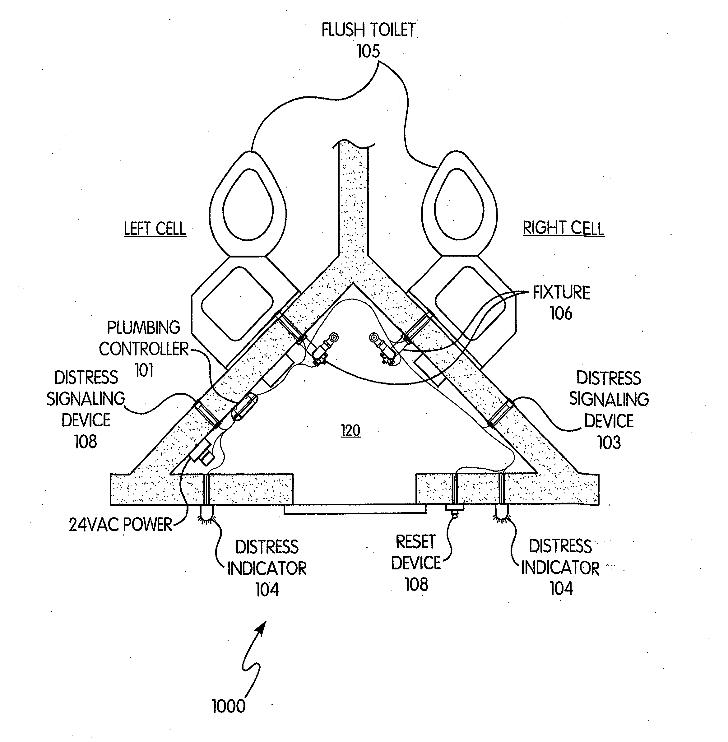
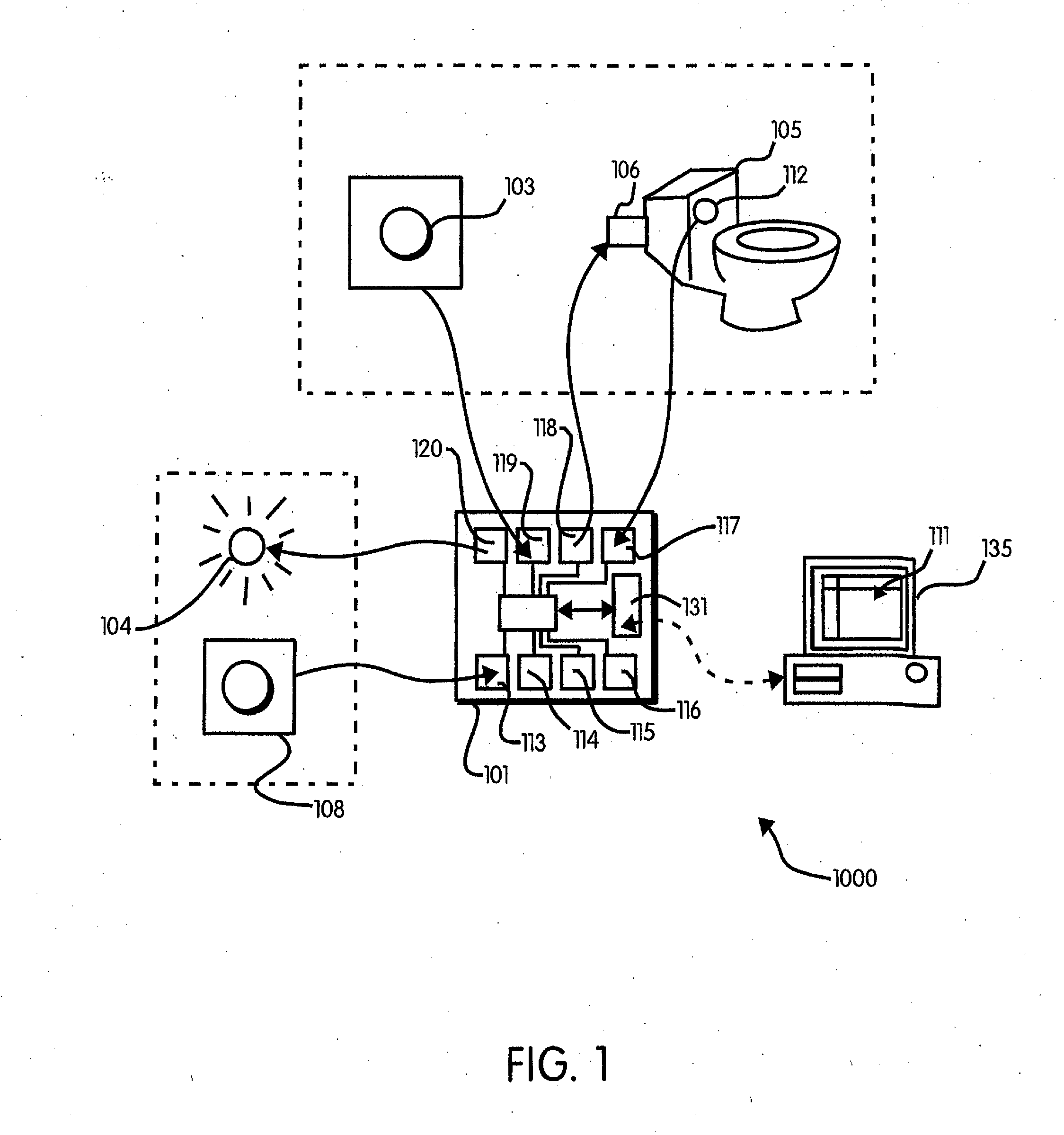
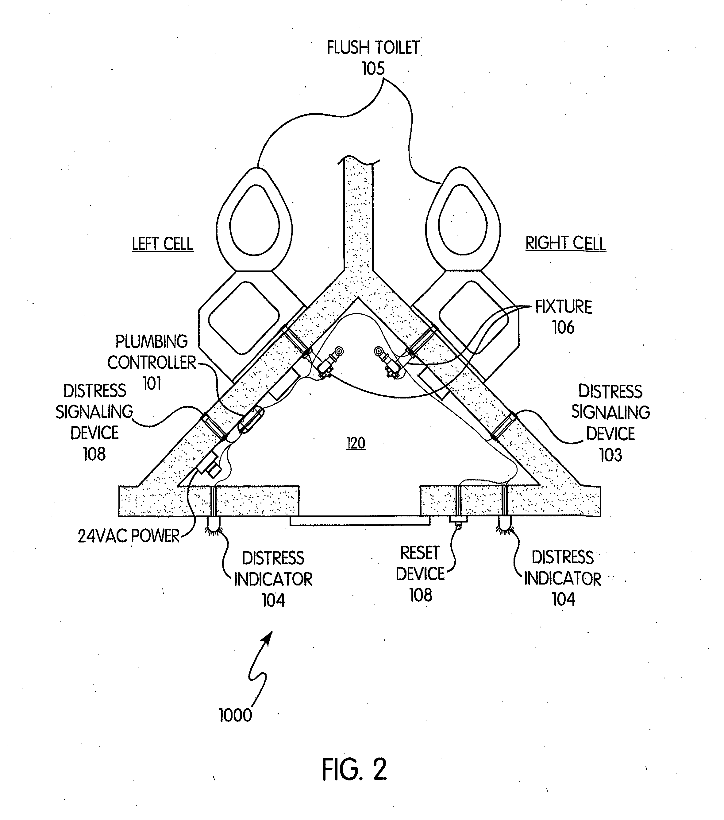
The present invention provides a distress signaling system for a plumbing control system that overcomes deficiencies of previous systems. The system includes a plumbing controller, a distress indicator, and a reset device. The system can deactivate the distress indicator based on a physical key being inserted into the reset device. The system may also include a management computer that displays a graphical user interface for controlling multiple electronic plumbing controllers. The technical effects of the invention include improved safety and reliability, as well as more efficient and effective response to distress signals in institutions.

Problems solved by technology

Retrofitting existing buildings and facilities can be costly, time-consuming, and difficult.
Further, implementing a duress system could present issues relating to inmate safety.
For example, the visibility of an inmate signaling for duress may cause the inmate to be targeted by others.

Method used


Image

  • Plumbing Control System With Distress Signal
  • Plumbing Control System With Distress Signal
  • Plumbing Control System With Distress Signal

Examples


Embodiment Construction

[0029]For purposes of the description hereinafter, the terms “upper”, “lower”, “right”, “left”, “vertical”, “horizontal”, “top”, “bottom”, “lateral”, “longitudinal” and derivatives thereof shall relate to the invention as it is oriented in the drawing figures. However, it is to be understood that the invention may assume various alternative variations and step sequences, except where expressly specified to the contrary. It is also to be understood that the specific devices and processes illustrated in the attached drawings, and described in the following specification, are simply exemplary embodiments of the invention. Hence, specific dimensions and other physical characteristics related to the embodiments disclosed herein are not to be considered as limiting.

[0030]As used herein, the terms “communication” and “communicate” refer to the receipt, transmission, or transfer of one or more signals, messages, commands, or other type of data. For one unit or device to be in communication ...


PUM


Abstract

A system, device, and method for communicating distress signals through a plumbing control system is provided. The system includes a plumbing controller configured to operate at least one plumbing appliance, at least one distress indicator in communication with the plumbing controller, and at least one distress sensor in communication with the plumbing controller. Activation of the at least one distress sensor causes activation of the at least one distress indicator.

Description

[0001]This application claims priority to United States Provisional Patent Application No. 61 / 917,550, filed Dec. 18, 2013, the entire content of which is incorporated herein by reference.BACKGROUND OF THE INVENTION[0002]1. Field of the Invention[0003]The present invention relates generally to plumbing control systems and, in particular, a system and method for incorporating a distress signal in a plumbing control system.[0004]2. Description of Related Art[0005]Federal, state, and / or local regulations may require correctional facilities to incorporate an inmate duress system to alert correctional staff to a situation. For example, regulations may require a duress push button to be located in a prison cell and be in electrical communication with a light-emitting diode (LED) located in an area visible to staff. Therefore, when actuated, the push button will activate the LED and signal that an inmate is under duress. A reset station is used to de-activate the LED after the duress situa...

Claims


Application Information

Patent Timeline
Patent Type & Authority Applications(United States)
IPC IPC(8): G08B25/01G08B25/10
CPCG08B25/10G08B25/016G08B5/36E03F7/02G01L19/12G05D7/0635G08B5/002G08B21/02G08B21/0469G08B21/08G08B21/084G08B21/18G08B23/00
Inventor BUSH, SHAWN D.
Owner SDB IP HLDG
Learn More