
Structure of textile

Inactive Publication Date: 2015-07-23
KINGS METAL FIBER TECH
View PDF4 Cites 7 Cited by
  • Summary
  • Abstract
  • Description
  • Claims
  • Application Information

AI Technical Summary

Benefits of technology

The present invention is about a special textile structure that includes two yarns, a RFID chip, and two antennas. The RFID chip is integrated with the yarns in a seamless way, and when touching it, users don't feel any unevenness, which makes it comfortable to wear.

Problems solved by technology

Such a conventional way of combining the RFID antenna with a textile generally suffers a major disadvantage that the RFID antenna may get broken or split when clothing is washed or stretched.
Another disadvantage is that the clothing with the RFID combined therein may cause perception of discomfort of irregularity.
These disadvantages simply lead to deviation from the expected functionality and achievement of the inclusion of RFID in clothing.

Method used


Image

  • Structure of textile
  • Structure of textile
  • Structure of textile

Examples


Embodiment Construction

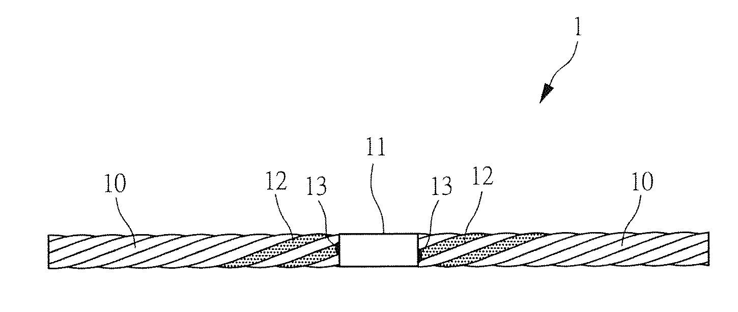
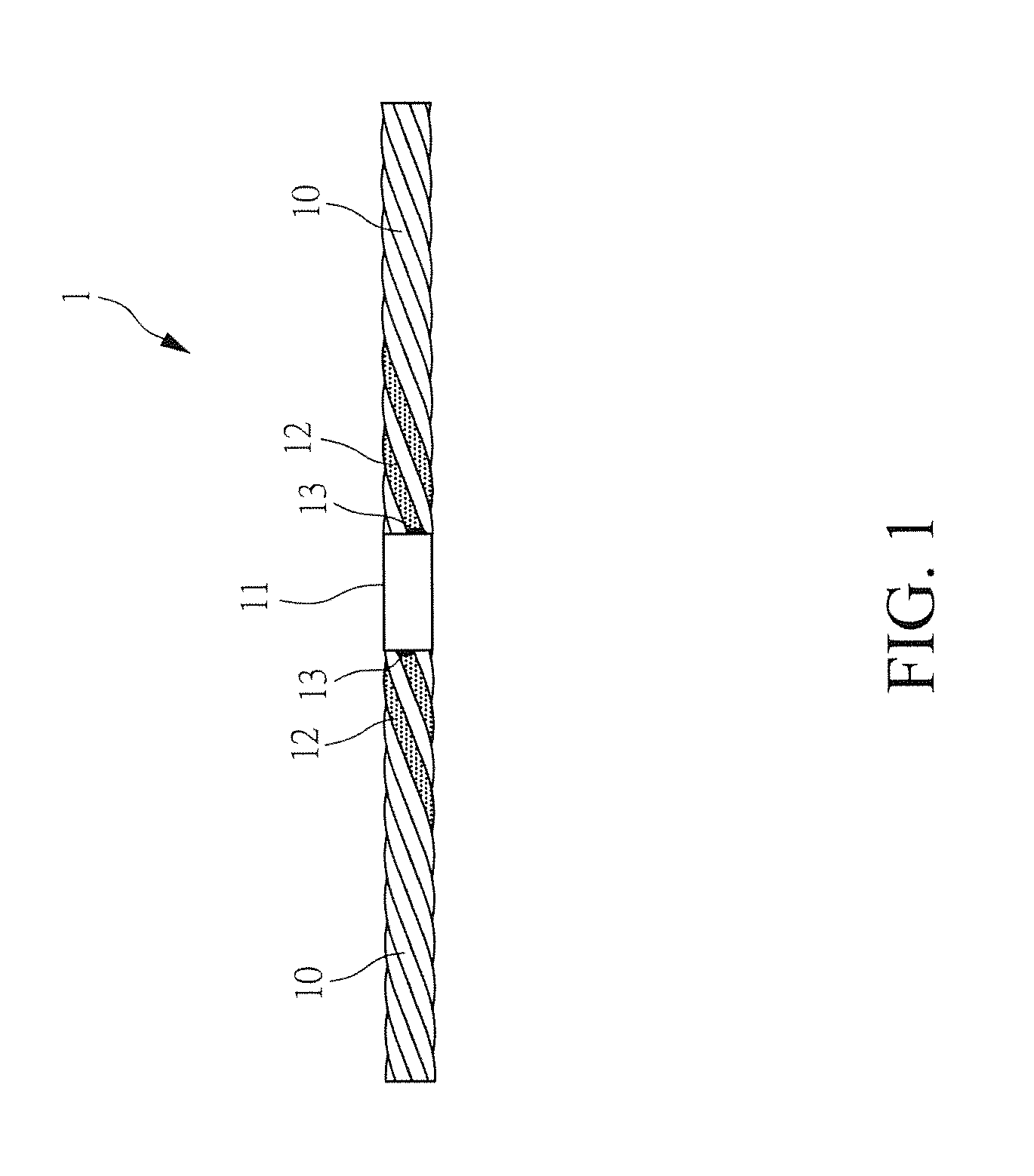
[0019]FIG. 1 is a schematic, partial enlarged view of a structure of a textile according to a first embodiment of the present invention. As shown in FIG. 1, the textile structure 1 comprises:

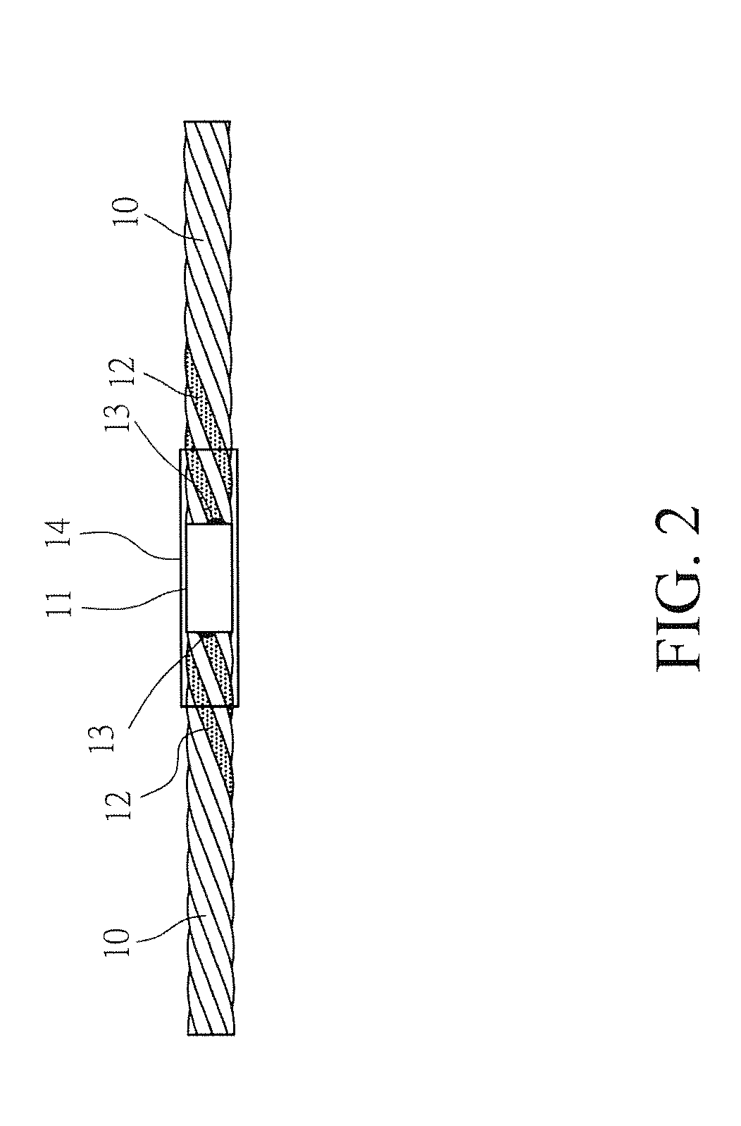
[0020]two yarns 10, a radio frequency identification (RFID) chip 11, and two antennas 12, wherein the antennas 12 are each electrically connected to the RFID chip 11 and connections between the antennas 12 and the RFID chip 11 each form a connection point 13 and the antennas 12 are respectively combined with the yarns 10.

[0021]In the instant embodiment, the antennas 12 are each twisted with the yarn to form a strand; otherwise an end of each of the antennas 12 is electrically connected to the RFID chip 11, while another end connected to the yarn 10, where the electrical connection between the antennas 12 and the RFID chip 11 can be for example soldering, press-to-fix, bonding, or laminating. However, the description given above is just a preferred embodiment of the present invention and should n...


PUM


Abstract

The present invention relates to a textile structure, which includes two yarns, a radio frequency identification (RFID) chip, and two antennas. The antennas are each electrically connected with the RFID chip. The antennas are respectively combined with the yarns. As such, with the combination of the yarns with the antennas, no tactile perception of irregularity will be sensed when a user touches and also, the comfortableness of wearing can be enhanced.

Description

FIELD OF THE INVENTION[0001]The present invention relates to a structure of a textile, and in particular to a structure of a textile that is formed of a combination of two yarns, a radio frequency identification (RFID) chip, and two antennas.BACKGROUND OF THE INVENTION[0002]Radio frequency identification (RFID) technology is a non-contact automatic identification technique, which enables automatic identification of and retrieval of related data an article through radio frequency signals. Although requiring a higher manufacturing cost than the traditional barcodes, RFID possesses various advantages that the barcodes do not provide, such as water resistance, magnetism resistance, low temperature resistance, extended life span, extended range of access, and ease of modification of data stored in RFID tags. The general technique of RFID is to establish bi-directional non-contact data transmission between a reader and a tag in radio frequency based wireless manner in order to realize the...

Claims


Application Information

Patent Timeline
IPC IPC(8): G06K19/077
CPCG06K19/07794G06K19/07762G06K19/027
Inventor HUANG, HONG-HSUCHEN, RENG-SHOSU, I-CHEN
Owner KINGS METAL FIBER TECH
Learn More