
One dimensional three way catalyst model for control and diagnostics

a catalyst model and three-dimensional technology, applied in the direction of electric control, machines/engines, instruments, etc., can solve the problems of utilizing a zero-dimensional model, requiring more processing power, and storing oxygen using a model that includes a plurality of partial differential equations in one or more dimensions, so as to reduce the breakthrough of emissions and increase the operating window about stoichiometric air-fuel.

Active Publication Date: 2015-07-23
FORD GLOBAL TECH LLC
View PDF1 Cites 15 Cited by
  • Summary
  • Abstract
  • Description
  • Claims
  • Application Information

AI Technical Summary

Benefits of technology

The patent is about controlling emissions in gas engines using a catalyst. The issue with this is that in real world driving, the engine may not always be running at the ideal air-fuel ratio. The patent proposes adjusting the fuel injection based on the oxidation state of the catalyst, which helps to optimize emissions control. By monitoring the catalyst and using a one-dimensional model, the method can make adjustments in real time to prevent excess emissions and improve fuel efficiency. The approach is also applicable to both partial and full volume catalyst systems. This method allows for a non-intrusive monitor for control and diagnostics, which is less dependent on sensor location. Overall, the patent presents a technical solution for controlling emissions in gas engines using a catalyst.

Problems solved by technology

However, the inventors have recognized an issue with the above approaches.
Determining the level of stored oxygen utilizing a model that includes a plurality of partial differential equations in one or more dimensions may be difficult to implement and may require more processing power than typically available in an engine controller.
Further, utilizing a zero dimensional model may neglect parameters and may not accurately predict emissions during cold start due to the reduced order of the model.

Method used


Image

  • One dimensional three way catalyst model for control and diagnostics
  • One dimensional three way catalyst model for control and diagnostics
  • One dimensional three way catalyst model for control and diagnostics

Examples


Embodiment Construction

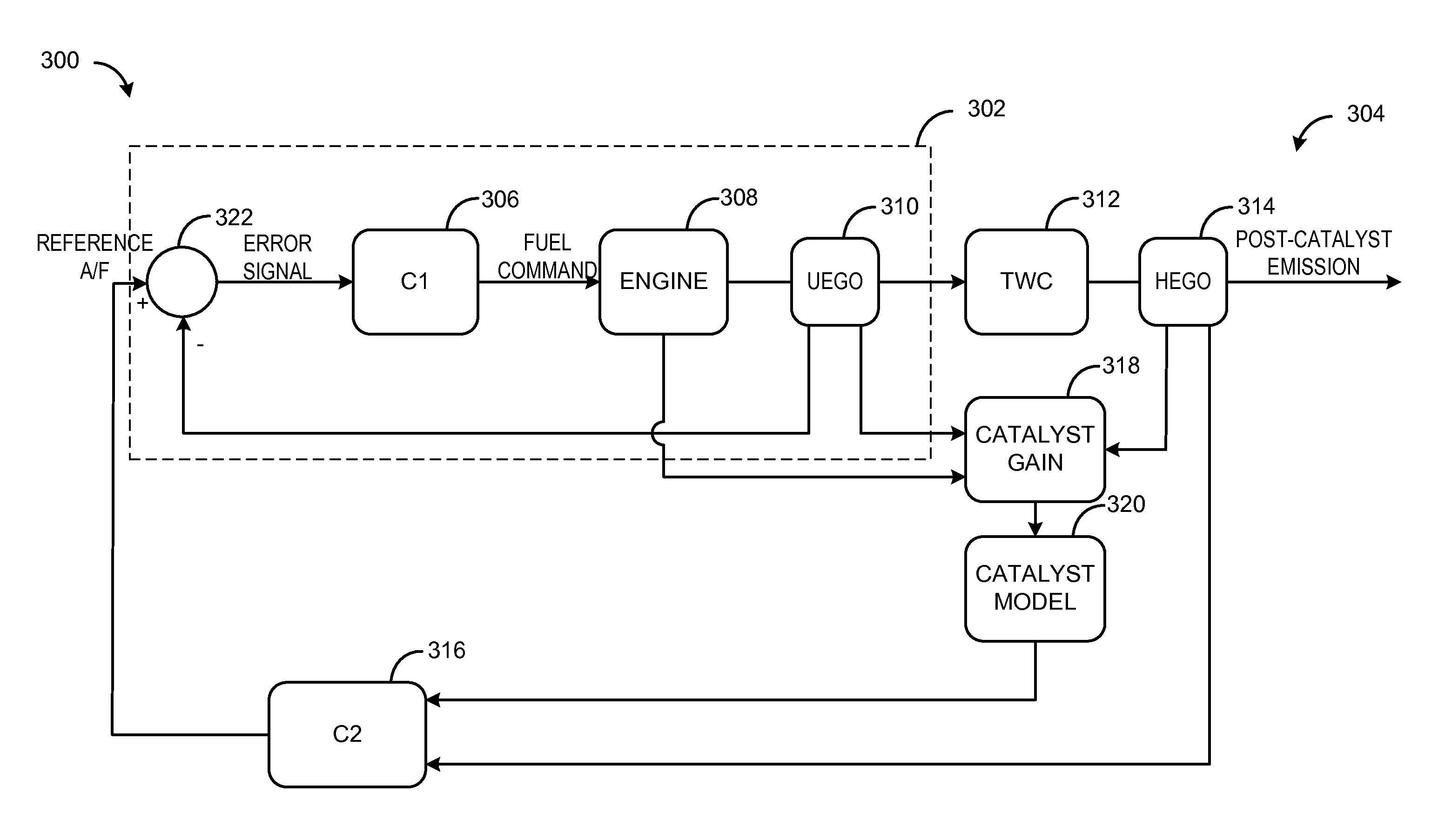
[0015]To reduce the breakthrough of emissions, catalysts may utilize oxygen storage material, for example ceria in the form of cerium oxide, to provide buffer for oxygen during rich or lean excursions. The air-fuel ratio entering the catalyst may be controlled such that the oxidation state of the catalyst is maintained at a desired level. In one example model of the present disclosure, the concentration of various exhaust gas species, such as H2, CO, NOx, HC, and O2, at the inlet through the outlet of the catalyst may be modeled using a simplified one-dimensional model grouping the various exhaust gas species into two or fewer mutually exclusive groups. The model accounts for complex catalyst dynamics, such as diffusion limitations and reaction in the washcoat and catalyst aging and gradients accounted for in internal and external mass transfer coefficients, and simplifies the dynamics into a set of equations averaged over space and time with a reduced number of chemical species ach...


PUM


Abstract

A method comprising adjusting a fuel injection amount based on a fractional oxidation state of a catalyst, the fractional oxidation state based on reaction rates of grouped oxidant and reductant exhaust gas species throughout a catalyst and a low-dimensional physics-based model derived from a detailed two-dimensional model to obtain a one-dimensional model averaged over time and space that accounts for diffusion limitations in the washcoat and accurately predicts emissions during cold start.

Description

FIELD[0001]The present disclosure relates to feedback control of air-fuel ratio in an internal combustion engine.BACKGROUND AND SUMMARY[0002]Exhaust gas emissions control in a gasoline engine utilizing a catalyst is most efficient when the catalyst feedgas air-fuel ratio is near stoichiometry. During real world operation of the gasoline engine, excursions from stoichiometry may occur. Ceria is commonly added to a catalyst to act as a buffer for oxygen storage to help curb the breakthrough of emissions and increase the operating window about the stoichiometric air-fuel ratio. The stored oxygen may be maintained at a desired set point based on catalyst monitor sensors and / or physics-based catalyst models.[0003]One approach to control and diagnose exhaust gas emissions utilizes a physics-based model to determine the level of stored oxygen in a catalyst which includes a plurality of partial differential equations in one or more dimensions with a plurality of exhaust gas species. Another...

Claims


Application Information

Patent Timeline
IPC IPC(8): F02D41/02G01M15/10
CPCG01M15/104F02D41/0235F02D2041/1472F02D41/0295F02D41/064F01N11/007F02D41/1441F02D41/1452F02D41/1454F02D41/1456F02D41/1458F02D41/1462F02D41/18F02D2200/0814F02D2200/0816F02D2200/101F01N3/10F01N3/101F01N2900/0406F01N2900/1624Y02A50/20Y02T10/12Y02T10/40
Inventor KUMAR, PANKAJMAKKI, IMAD HASSAN
Owner FORD GLOBAL TECH LLC
Learn More