
Integral drip irrigation emitter with an easy spreadable exit pool

a technology of drip irrigation and emitter, which is applied in the field of integrated drip irrigation emitters, can solve the problems of limiting the possibility, clogging the exit length, and limiting the possibility,

Active Publication Date: 2015-07-23
RIVULIS IRRIGATION
View PDF4 Cites 32 Cited by
  • Summary
  • Abstract
  • Description
  • Claims
  • Application Information

AI Technical Summary

Benefits of technology

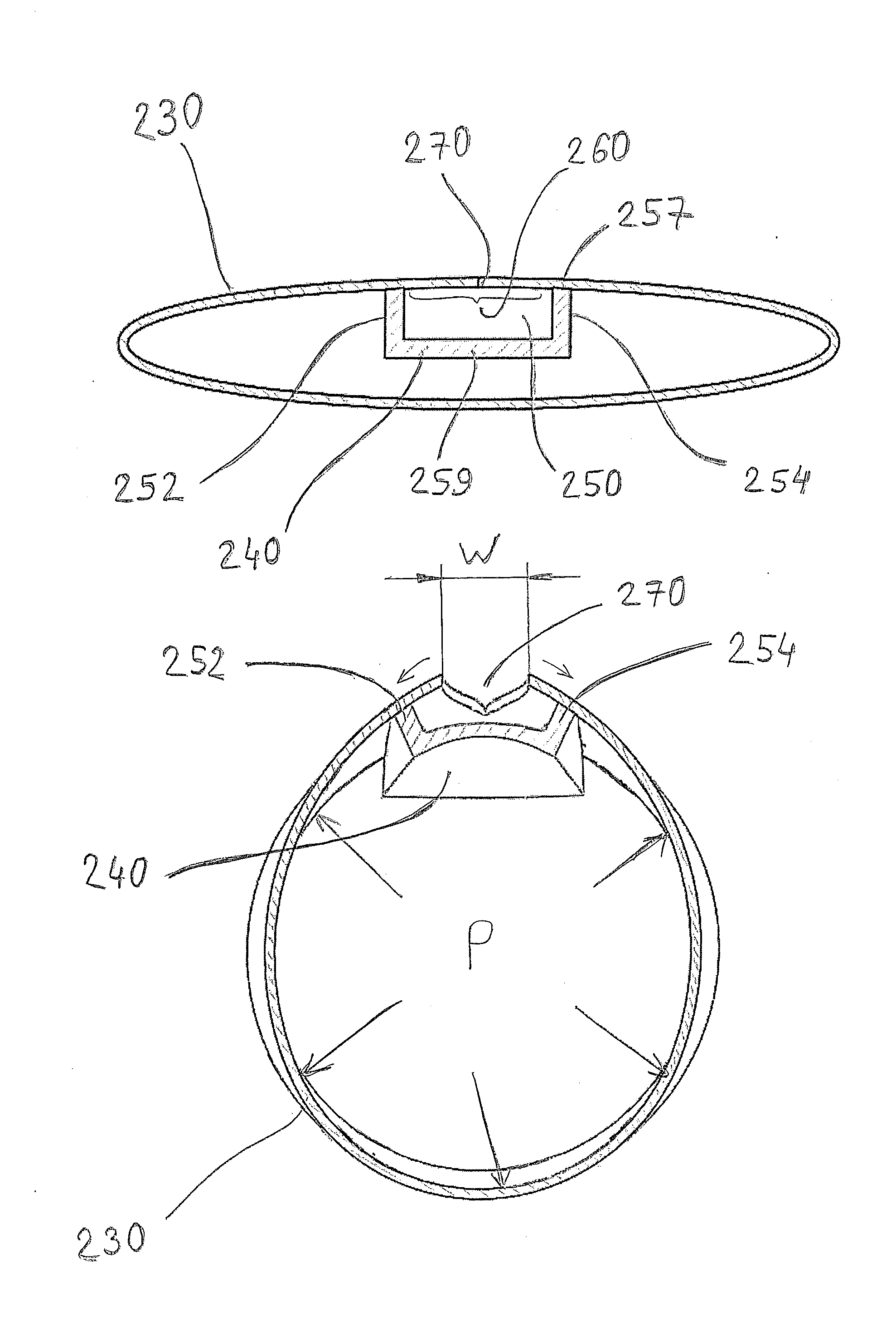
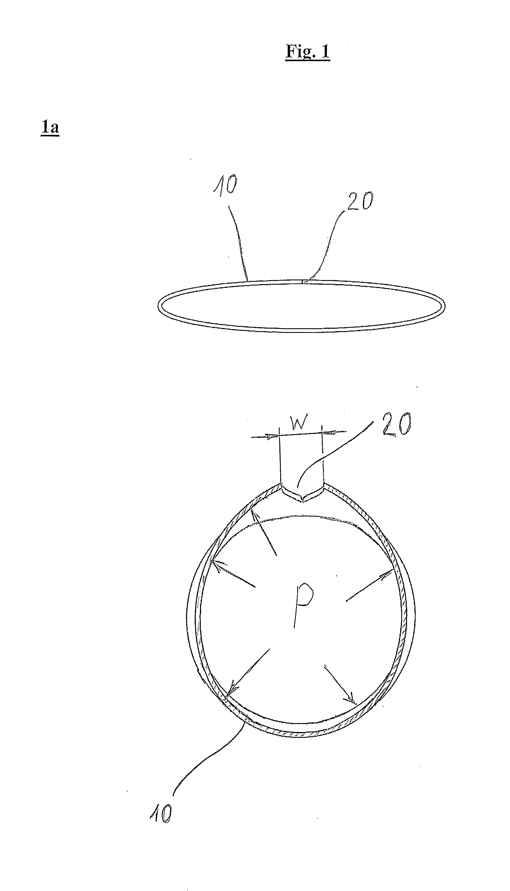
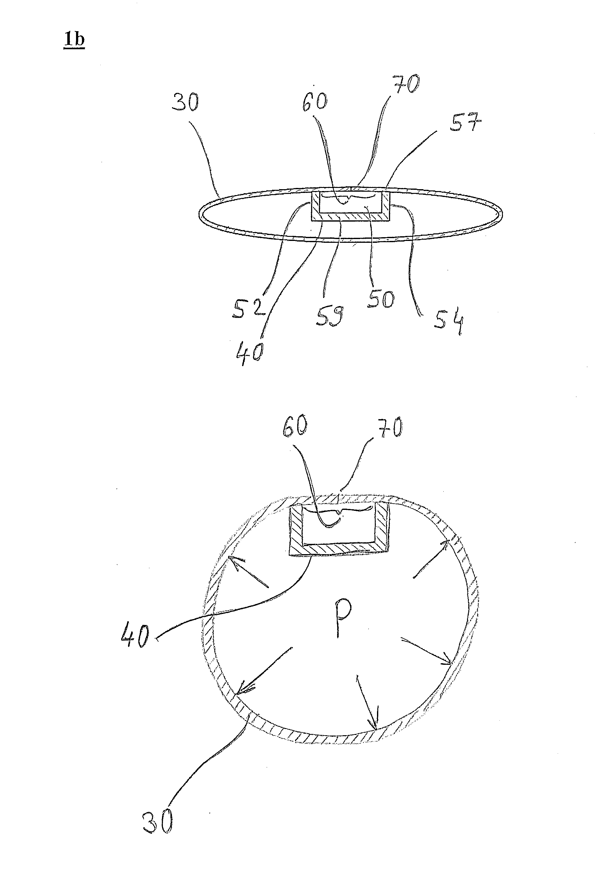
The invention is about a new type of drip irrigation emitter that has a unique feature. When water pressure in a hose increases, the emitter spreads its legs and opens the slit that serves as a water outlet, allowing water to flow through. When the pressure decreases, the slit closes, allowing the emitter to self-close and stop water from flowing. The emitter is made from a soft raw material, and its design allows it to elastically move and close the slit when water pressure decreases. This invention provides improved control and efficiency in drip irrigation systems.

Problems solved by technology

Embedding the hoses in the ground is liable to worsen the clogging problem when the water pressure in the hose is reduced.
However, when we consider an integral, discrete drip irrigation emitters, that are formed, each one of them, with a water exit “pool”, we will find that from the outset the length dimension of the exit “pool” limits the possibility to implement at the wall of the hose, a slit that would be at appropriate length given the length dimension of the pool.
The flow rate from the dripper would hence be dependent also on the resistance to the flow presented by the slit (a resistance that can vary in accordance with, for example, the thickness of the wall of the hose, environmental temperature and so on), and this creates difficulties in achieving accurate design (planning), (for example, would necessitates increasing the minimal working pressure of the drip emitter or would mandate forming a relatively long slit).
Moreover, a bi-components structure is deemed to be relatively expensive, limited by the variety of materials that can be used (selected) (the two materials have to be suited to co-extrusion manufacturing process), and the elastomeric component might be harmed by creep during long service and also due to temperature variations.

Method used


Image

  • Integral drip irrigation emitter with an easy spreadable exit pool
  • Integral drip irrigation emitter with an easy spreadable exit pool
  • Integral drip irrigation emitter with an easy spreadable exit pool

Examples


Embodiment Construction

[0051]Reference is being made to FIGS. 3 to 7. FIG. 3 constitutes a view in perspective of an example of a drip emitter 340 in accordance with the invention. FIG. 4 constitutes a view in perspective of cross section a-a that was marked in FIG. 3. FIG. 5. constitutes a side view of the cross section a-a that was marked in FIG. 3. FIG. 6 shows a view in perspective of drip irrigation emitter 340 on its side that is adapted for affixing onto the inner wall of the hose (that is not illustrated). FIG. 7 depicts a view of drip irrigation emitter 340 on its side that is adapted for affixing onto the inner wall of the hose (that is not illustrated).

[0052]On seeing the figures, any professional would understand that drip irrigation emitter 340 is a “boat” like discrete drip irrigation emitter of the kind that is adapted to being integrally installed within a hose (that is not illustrated). The drip emitter is a single component device, wherein its body component has an essentially rectangula...


PUM


Abstract

An integral, discrete, drip irrigation emitter that comprises means for facilitating spreading of its water exit “pool” U configured, in cross section, “legs”, so that after affixing the drip emitter onto the inner wall surface of the hose, and following water pressure increase within the hose, an elastic movement of a sector of the hose's wall that is framed and delineated as a consequence of affixing the circumferential rim of the exit pool onto the inner wall of the hose, will take place onto opening a water outlet opening, and from the time the water pressure in the hose decreases, closing of the water outlet opening would occur, and a drip irrigation hose embedding at least one such emitter in it, and a general method for opening and closing water outlet openings in such hose, wherein the opening and closing is performed in accordance with and in correlation to the water pressure prevailing in the hose.

Description

FIELD OF THE INVENTION[0001]The invention, the subject matter of this application, is found in the field of integral drip irrigation emitters (known also as—drippers, drip emitters), namely—in the field of drippers that are formed as discrete units and are integrated inside a hose, positioned along its length with spaces one from the other, wherein they are affixed onto the inner wall of the hose and the water outlet openings are formed on their sides in the wall of the hose and connect for water flow passage from the drip irrigation emitters to the external side of the hose (to the agricultural area that is designated / intended to be irrigated).BACKGROUND OF THE INVENTION[0002]Integral drip irrigation emitters, whose surface areas are adapted for affixing onto the inner wall of the hose, are well known and recognized, wherein water exit “pool” (also known as water outlet basin) is formed on them. Naturally, a water outlet opening that, as said, is formed on its side in the hose's wa...

Claims


Application Information

Patent Timeline
Patent Type & Authority Applications(United States)
IPC IPC(8): A01G25/02E02B1/00
CPCE02B1/00A01G25/02A01G25/023Y02A40/22A01G25/06
Inventor EINAV, ZVI
Owner RIVULIS IRRIGATION
Learn More