
Solid-State Lighting Dimming

a technology of solid-state lighting and dimming, which is applied in the direction of electric variable regulation, process and machine control, instruments, etc., can solve the problems of inability to directly control the dimming of ssl systems, inability to dim the light produced by, and inability to use analog dimmer switches commonly found in homes and offices to control dimming of conventional incandescent lighting sources. to achieve the effect of simple “current control” approach

Active Publication Date: 2015-07-16
MCCUNE JR EARL W
View PDF15 Cites 4 Cited by
  • Summary
  • Abstract
  • Description
  • Claims
  • Application Information

AI Technical Summary

Benefits of technology

This patent is about controlling dimming in solid-state lighting ( SSL) systems. The invention uses an AC scaling unit to control the dimming of the SSL driver, and a dim control signal generating circuit to generate a dim control signal based on the scaled AC voltage. A current control circuit adjusts the current flowing through the string of light-emitting devices, resulting in dimming over a range of dimming values. To extend the dimming range to even lower light levels, a combination of current control and PWM-based dimming is used. This approach avoids flicker and minimal electromagnetic interference, making it ideal for use in low-light environments such as movie theaters.

Problems solved by technology

Although SSL technology is superior to conventional lighting technologies in many respects, one well-known problem with its use relates to the ability to dim the light produced by the LEDs.
Unfortunately, because LEDs are nonlinear devices, the conventional analog dimmer switches commonly found in homes and offices to control dimming of conventional incandescent lighting sources cannot be used to directly control dimming in SSL systems.
However, under some circumstances it can undesirably produce flicker and electromagnetic interference (EMI).
Flicker, is particularly perceptible when the duty cycles of the control signal are low, and it can cause or induce headaches, blurred vision, eyestrain and other health-related discomforts and disorders.
EMI can also be problematic since it can interfere with reception in radios and degrade the performance of other electronic devices.
Additionally, PWM-based dimming is capable of dimming only over a limited dynamic range.
However, generating very narrow pulses and designing driver circuitry capable of responding to very narrow pulses is difficult and in some circumstances even impracticable.

Method used


Image

  • Solid-State Lighting Dimming
  • Solid-State Lighting Dimming
  • Solid-State Lighting Dimming

Examples


Embodiment Construction

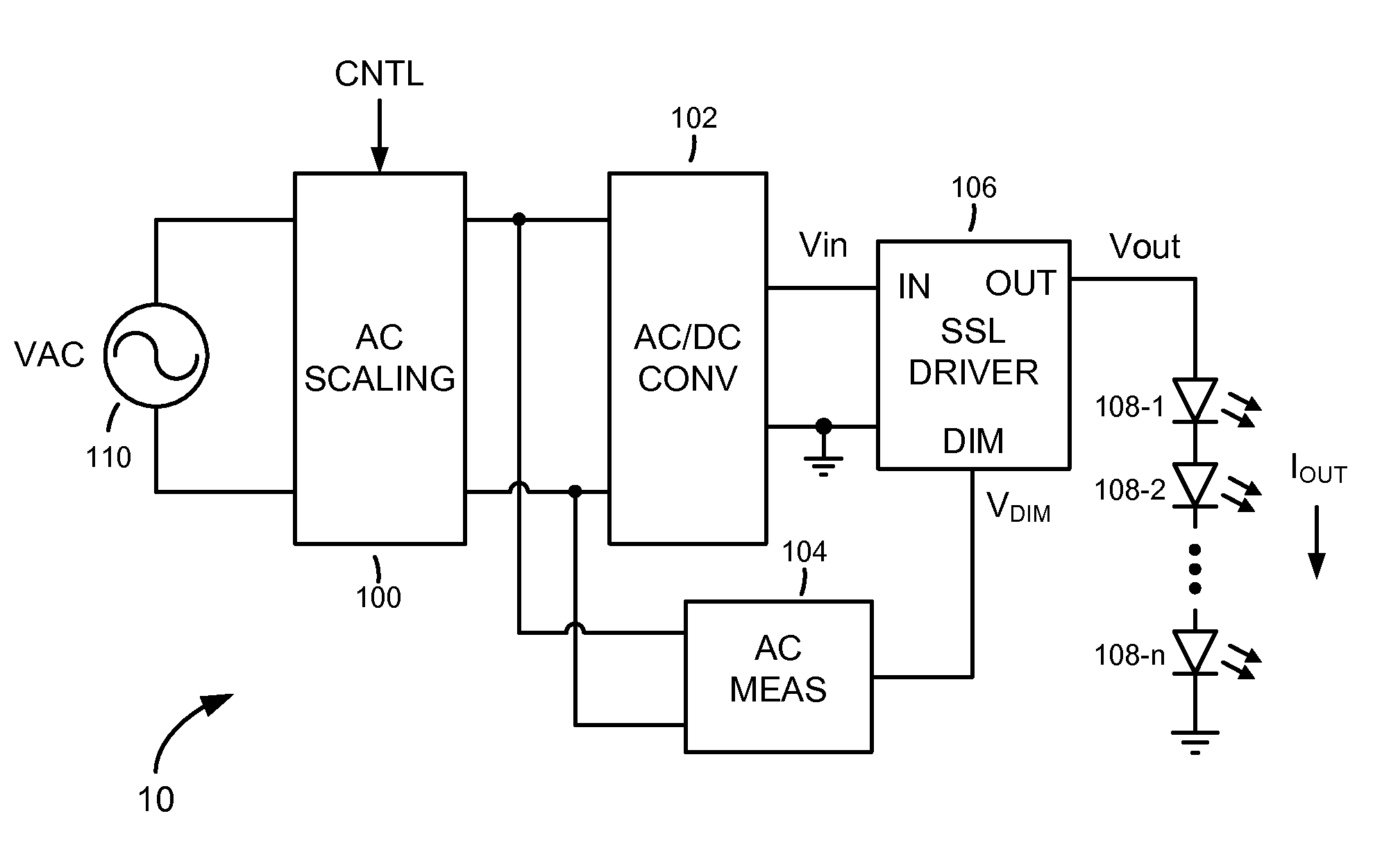
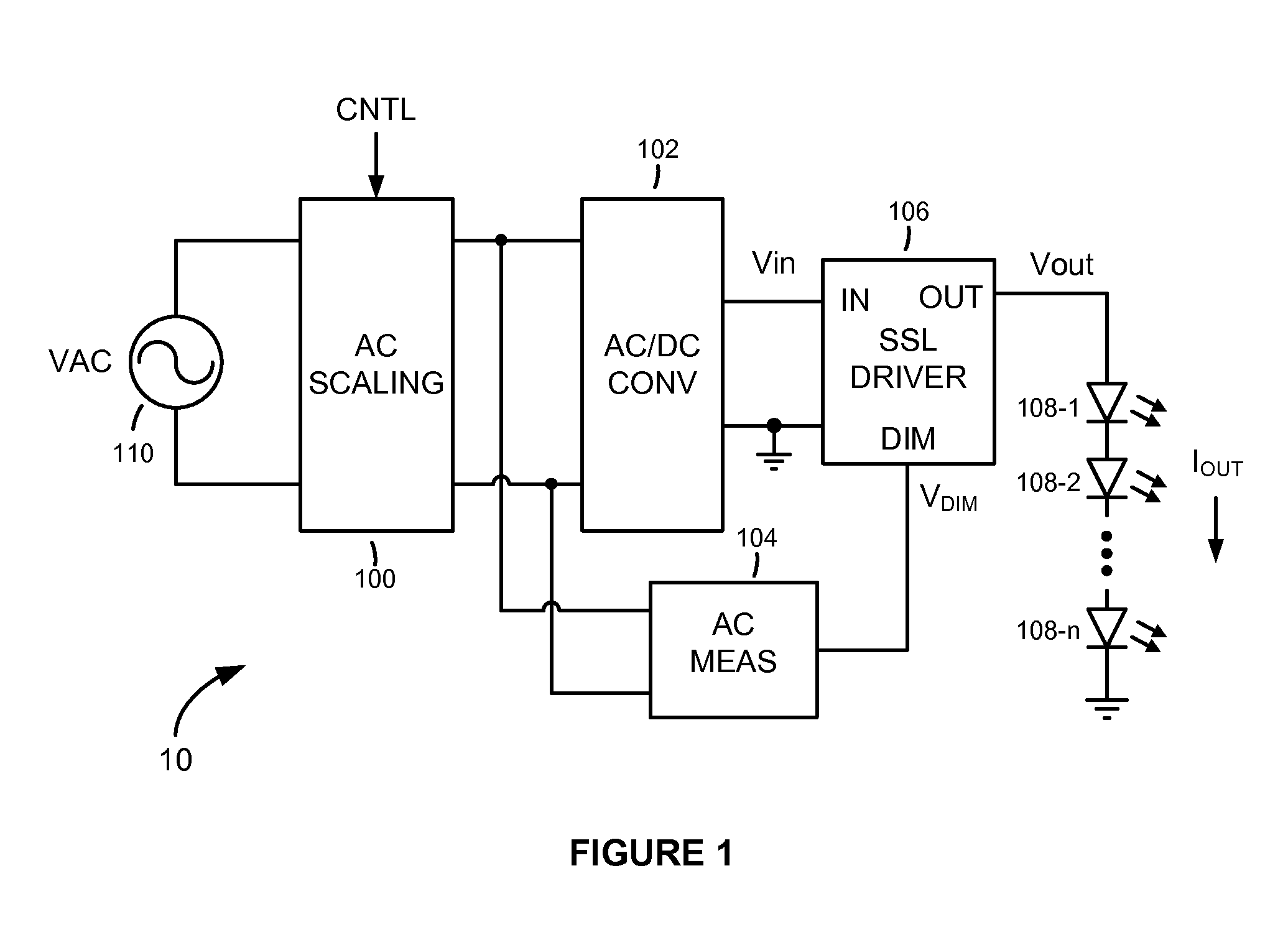
[0020]Referring to FIG. 1, there is shown a solid-state lighting (SSL) system 10 with dimming capability, according to an embodiment of the present invention. The SSL system 10 comprises an alternating current (AC) scaling unit 100, an alternating current to direct current (AC / DC) converter 102, an AC measuring unit 104, an SSL driver 106, and one or more light-emitting devices (e.g., light-emitting diodes (LEDs)) 108-1, 108-2, . . . , 108-n. The AC scaling unit 100 is connected between an AC power source 110 (such as the AC mains, for example) and the AC / DC converter 102, and is configured to scale the AC input voltage VAC supplied by the AC power source 110 to a scaled voltage determined by a scaling control signal CNTL. The AC / DC converter 102 is connected between the AC scaling unit 100 and the SSL driver 106, and serves to convert the scaled AC voltage produced at the output of the AC scaling unit 100 to a DC voltage Vin, which is applied to the input IN of the SSL driver 106. ...


PUM


Abstract

A solid-state lighting (SSL) system having dimming capability includes an SSL driver having a current control circuit configured to control current flow and, consequently, the brightness of light emitted by a light-emitting load. The magnitude of current flowing through the light-emitting load is set and controlled depending on a dim control signal, which is generated based on the value of a scaled alternating current (AC) power signal. The scaled AC power signal is generated by an AC scaling unit, which scales an input AC power signal provided by an AC power source. The extent to which the input AC power signal is scaled determines the value of the dim control signal and, consequently, the magnitude of current flow and resultant dimming of the light-emitting load. Pulse-width modulation of the light-emitting load current may be optionally combined with the current-control-based dimming to widen the overall dimming range.

Description

FIELD OF THE INVENTION[0001]The present invention relates in general to solid-state lighting (SSL) systems, and in particular to dimming light emitted by light-emitting devices of SSL systems.BACKGROUND OF THE INVENTION[0002]Solid-state lighting (SSL) is rapidly becoming a dominant lighting technology and is expected to largely displace most other conventional lighting technologies, such as incandescent and fluorescent lighting, in the not too distant future. SSL is a superior lighting technology since it employs light-emitting diodes (LEDs), which are energy efficient, long-lasting, and durable.[0003]Although SSL technology is superior to conventional lighting technologies in many respects, one well-known problem with its use relates to the ability to dim the light produced by the LEDs. Dimming is desirable since it helps conserve energy. It also allows the ambiance of an environment to be altered. Unfortunately, because LEDs are nonlinear devices, the conventional analog dimmer sw...

Claims


Application Information

Patent Timeline
Patent Type & Authority Applications(United States)
IPC IPC(8): H05B33/08H05B44/00
CPCH05B33/0845H05B33/0809H05B45/10H05B45/37Y02B20/30
Inventor MCCUNE, JR., EARL W.
Owner MCCUNE JR EARL W
Learn More