Eureka AIR delivers breakthrough ideas for toughest innovation challenges, trusted by R&D personnel around the world.

RFID device, methods and applications

a technology of rfid tags and backscattering, applied in the field of indoor realtime locating systems, can solve the problems of poor accuracy, inconvenient short-range time of flight (tof), and difficulty in passive cw phase ranging by backscattering rfid tags

Active Publication Date: 2015-07-16
CORNELL UNIVERSITY
View PDF10 Cites 20 Cited by
  • Summary
  • Abstract
  • Description
  • Claims
  • Application Information

AI Technical Summary

Benefits of technology

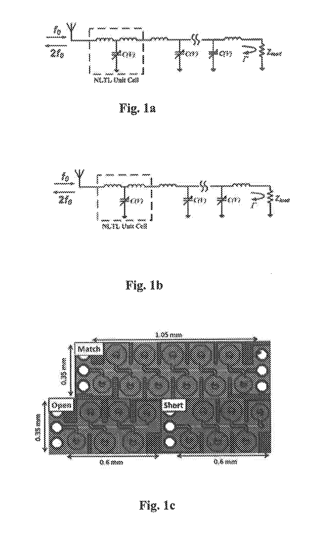
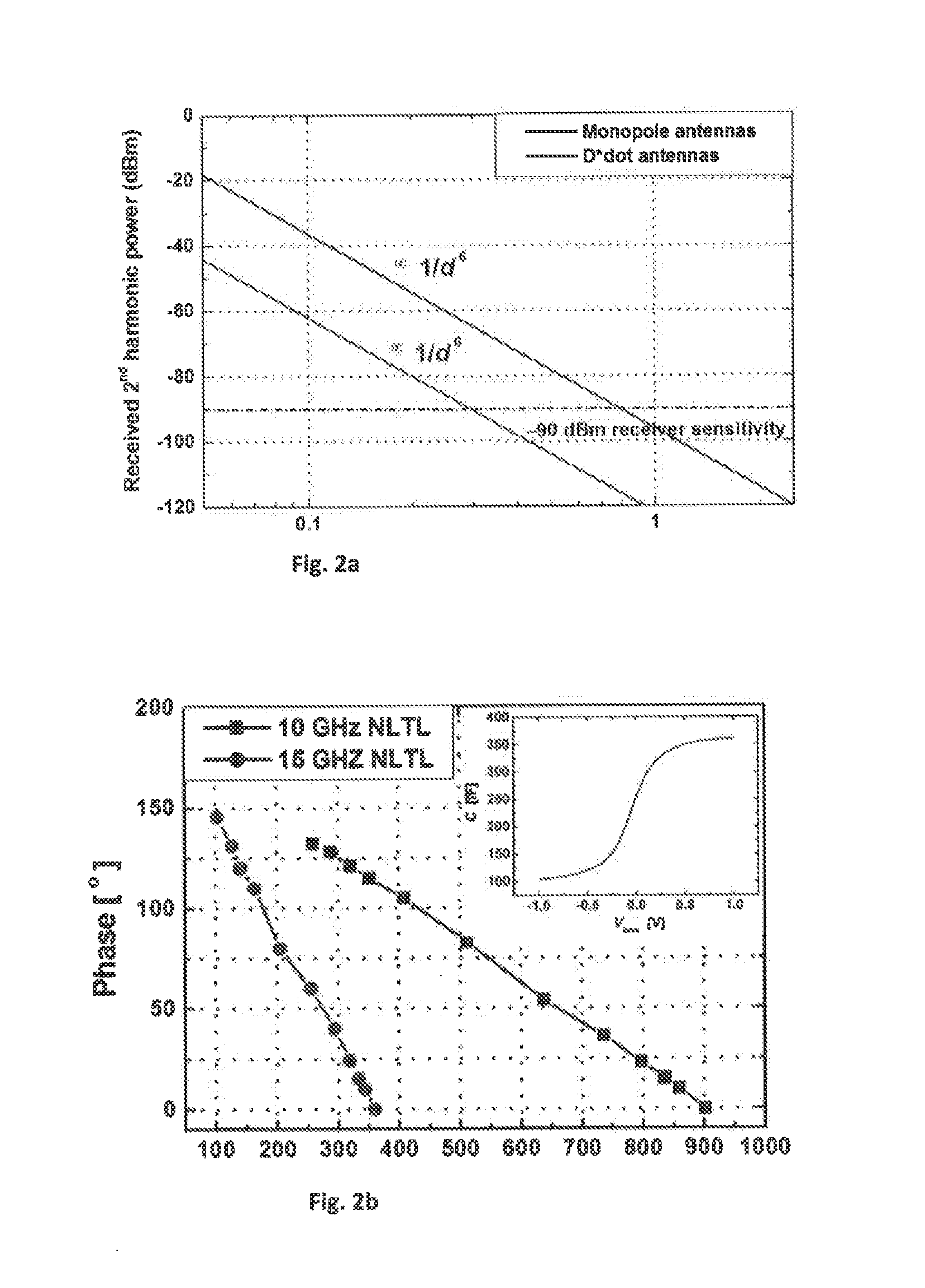
The patent text describes a system and method for ranging in indoor environments with high accuracy. The system includes a sensor tag with a nonlinear transmission line that generates harmonic signals when illuminated by a transceiver. The sensor tag is attached to a person or object. The system uses coordinated reading of the harmonic signals from the sensor tag by multiple antennas to determine the person or object's location based on the phases and magnitudes of the signals. The system is undisturbed by multi-path interference and resolves cycle ambiguity to accurately locate the sensor tag. The technical effect of this system is high accuracy and precision in indoor ranging with minimal interference and cycle ambiguity.

Problems solved by technology

Among RFID ranging methods, received signal strength (RSS) can work over large areas, but suffers from poor accuracy.
Time of flight (TOF) is not suitable for short range due to the difficulty in measuring small round-trip time delay.
However, in indoor environment, passive CW phase ranging by backscattering RFID tags can be challenging.
Physically, phase errors caused by multi-path interference are severe in offices and other indoor locales.
Poor isolation between transmitting and receiving ends brings strong self-interference that can also smear phase detection.
Neighboring readers can also cause strong interference without effective solution by synchronization.
Another limitation comes from signal processing.
Although CW can be accurate, cycle ambiguity exists when distance is longer than one wavelength.
Although RFID tags with harmonic generation have been proposed, the proposed tags do not address cycle ambiguity.

Method used


Image

  • RFID device, methods and applications
  • RFID device, methods and applications
  • RFID device, methods and applications

Examples


Embodiment Construction

[0021]The following detailed description is of the best currently contemplated modes of carrying out these teachings. The description is not to be taken in a limiting sense, but is made merely for the purpose of illustrating the general principles of these teachings, since the scope of these teachings is best defined by the appended claims. Although the teachings have been described with respect to various embodiments, it should be realized these teachings are also capable of a wide variety of further and other embodiments within the spirit and scope of the appended claims.

[0022]As used herein, the singular forms “a,”“an,” and “the” include the plural reference unless the context clearly dictates otherwise.

[0023]Except where otherwise indicated, all numbers expressing quantities of ingredients, reaction conditions, and so forth used in the specification and claims are to be understood as being modified in all instances by the term “about.”

[0024]“Trilateration,” as used herein, is th...


PUM


Abstract

Systems and methods for ranging in indoor environment that are accurate and that are substantially undisturbed by multipath interference. The method includes illuminating a sensor tag with electromagnetic radiation generated from a transceiver; the transceiver are being located a distance away from the sensor tag; the sensor tag comprising at least one nonlinear transmission line (NLTL) for broadband harmonic generation, receiving backscattered electromagnetic radiation from the at least one NLTL at three or more locations; coordinates of the three or more locations being known, obtaining from the phase and magnitude outputs at a second harmonic and at least one sub harmonic of second harmonic, a distance from the sensor tag to each of the three or more locations and trilaterating a location of the sensor tag.

Description

BACKGROUND[0001]The present disclosure is directed to indoor real-time locating systems (RTLS), methods, and associated applications.[0002]Short-distance, high accuracy ranging is important for many applications such as indoor navigation, body area network (BAN) and unobstructed motion tracking. Meanwhile, recent development in radio-frequency identification (RFID) systems for efficient asset management has made RFID tags and associated devices widely available with low-cost and low-energy consumption. Among RFID ranging methods, received signal strength (RSS) can work over large areas, but suffers from poor accuracy. Time of flight (TOF) is not suitable for short range due to the difficulty in measuring small round-trip time delay. Continuous-wave (CW) phase-based methods using single-tone carriers are preferred for their high accuracy and simple architecture.[0003]However, in indoor environment, passive CW phase ranging by backscattering RFID tags can be challenging. Physically, p...

Claims


Application Information

Patent Timeline
Patent Type & Authority Applications(United States)
IPC IPC(8): G01S13/38G01S13/84G06K7/10
CPCG01S13/38G01S2013/466G01S13/84G06K7/10366G01S13/878
Inventor KHAN, EDWIN C.MA, YUNFEI
Owner CORNELL UNIVERSITY
Why Eureka
Eureka Blog
Learn More