Eureka AIR delivers breakthrough ideas for toughest innovation challenges, trusted by R&D personnel around the world.

System and method for communication in wireless power supply systems

a wireless power supply and wireless communication technology, applied in the direction of inductance, energy consumption reduction, high-level techniques, etc., can solve problems such as data collision and data loss, affecting performance, and other undesirable issues, and achieve the effect of preventing data collision

Active Publication Date: 2015-07-09
PHILIPS IP VENTURES BV
View PDF10 Cites 48 Cited by
  • Summary
  • Abstract
  • Description
  • Claims
  • Application Information

AI Technical Summary

Benefits of technology

The present invention is about wireless power supplies that can communicate with remote devices. The system helps to prevent data collisions and ensures that information sent from one device doesn't overlap with that of another device. This is done by controlling the timing of communication between the wireless power supply and the remote devices. This stable communication allows the wireless power supply to control the supply of power to the remote devices based on their operating parameters. Overall, the invention provides a simple and effective way to ensure successful communication between a wireless power supply and remote devices.

Problems solved by technology

In a further example, the presence of parasitic metal in range of the wireless power supply may affect performance or present other undesirable issues.
However, with multiple remote devices attempting to communicate, there is a possibility of data collision and data loss.
Loss of communication may prevent the devices from communicating power requirements and possibly result in too much or too little power being transferred, potentially damaging a device.
There also may be too much or too little power transferred if one or more of the remote devices is incapable of communicating information to the wireless power supply.
These systems, however, add cost and complexity to the remote devices and the wireless power supply.
And, the long distance capabilities of RF communication systems may result in communication with remote devices not present near the wireless power supply.
For example, if two wireless power supplies, each associated with a remote device to be charged, are in the same room and use an RF communication system, there may be communication errors with the remote devices during power transfer.

Method used


Image

  • System and method for communication in wireless power supply systems
  • System and method for communication in wireless power supply systems
  • System and method for communication in wireless power supply systems

Examples


second embodiment

D. Second Embodiment

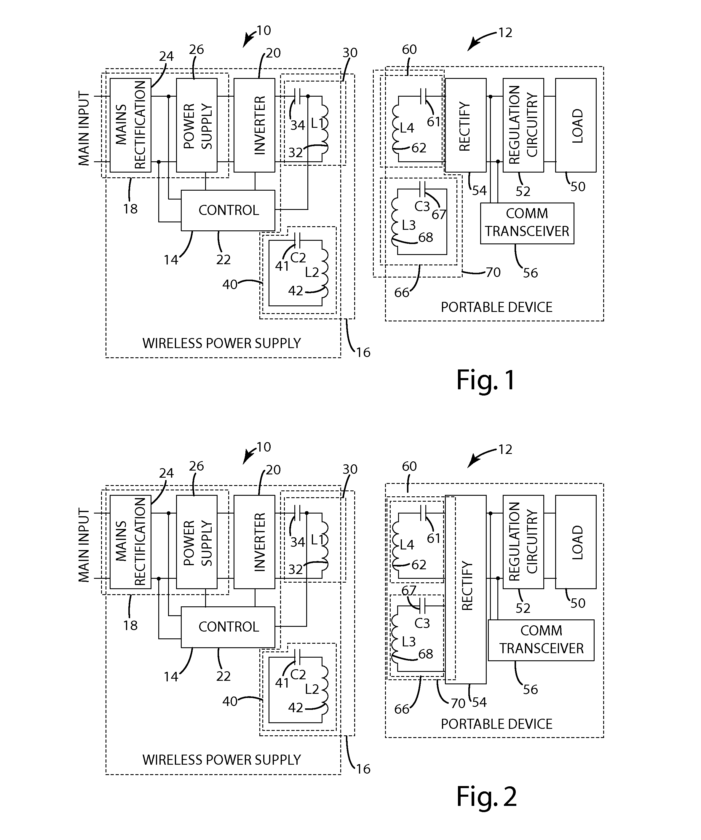
[0077]In a second embodiment of the present invention, the system and method of a wireless power supply and a remote device are similar to those described herein with respect to the wireless power supply 10 and remote device 12, with several exceptions. The second embodiment may use a system and method similar to those of the current embodiment, and may further include a remote device 12 configured to detect how many remote devices are placed on the same wireless power supply 10 and to vary their power control methods based on the number of devices detected.

[0078]In this embodiment, when a remote device 12 chooses a time slot, it checks the following sync communication packer from the wireless power supply 10 to determine if the time slot chosen is now acknowledged by the wireless power supply 10 as being occupied. However, if two remote devices 12 have chosen the same time slot, and the wireless power supply 10 is able to receive a full communication packet from...

third embodiment

E. Third Embodiment

[0083]In a third embodiment of the present invention, the system and method of a wireless power supply and a remote device are similar to those described herein with respect to the wireless power supply 10 and remote device 12, with several exceptions. The third embodiment may use a system and method similar to those of the current embodiment, and may further include a wireless power supply 10 configured to request that a remote device 12 reduce its power consumption. The wireless power supply 10 may request that a remote device 12 reduce its consumption if certain criteria are met: (a) if the maximum power available to the wireless power supply 10 is reached, (b) if the wireless power supply 10 determines there are foreign objects within the active magnetic field, (c) if another remote device 12 requests an urgent desire to reduce power in the field, or (d) if the wireless power supply 10 detects an over temperature situation within itself.

fourth embodiment

F. Fourth Embodiment

[0084]In a fourth embodiment of the present invention, the system and method of a wireless power supply and a remote device are similar to those described herein with respect to the wireless power supply 10 and remote device 12, with several exceptions. The fourth embodiment may use a system and method similar to those of the current embodiment, and may further include a remote device 12 that may vary the impedance of its modulation element(s) depending on the configuration.

[0085]In this embodiment, for example, if the remote device 12 desires to send a high priority message, it may use a separate or additional modulator that causes a modulation large enough to overpower the modulators of other remote devices 12, and may decide to send the information at any point in time, rather than waiting for its assigned time slot. The remote device 12 may also request that the wireless power supply 10 resend a sync communication packet if the remote device 12 has determined...


PUM


Abstract

The present invention relates to wireless power supplies adapted to supply power and communicate with one or more remote devices. The systems and methods of the present invention generally relate to a communication timing system that may ensure information being communicated does not overlap with that of another device, preventing data collisions and information from going undetected. With information being communicated in a way that addresses or avoids potential communication issues in multiple device systems, the wireless power supply may control operation to effectively supply wireless power.

Description

BACKGROUND OF THE INVENTION[0001]The present invention relates to wireless power supply systems, and more particularly to systems and methods for communicating in a wireless power supply system.[0002]Many conventional wireless power supply systems rely on inductive power transfer to convey electrical power without wires. A typical inductive power transfer system includes an inductive power supply that uses a primary coil (or a transmitter) to wirelessly transfer energy in the form of a varying electromagnetic field and a remote device that uses a secondary coil (or a receiver) to convert the energy in the electromagnetic field into electrical power. Recognizing the potential benefits, some developers have focused on producing wireless power supply systems with adaptive control systems. Adaptive control systems may give the wireless power supply the ability to adapt operating parameters over time to maximize efficiency and / or control the amount of power being transferred to the remot...

Claims


Application Information

Patent Timeline
IPC IPC(8): H02J5/00H04B5/00
CPCH02J5/005H04B5/0037H04B5/0031H02J50/402H02J50/80H02J50/12H04B5/263H04B5/72H04B5/79H02J50/60Y02D30/70
Inventor TAYLOR, JOSHUA B.NORCONK, MATTHEW J.MOORE, COLIN J.MOES, BENJAMIN C.VEISEH, MERDADLIFF, DALE R.BLAHA, MARK A.AMISTADI, JASON L.
Owner PHILIPS IP VENTURES BV
Why Eureka
Eureka Blog
Learn More