
Transmission control method and device

Inactive Publication Date: 2008-01-31
FUJITSU LTD
View PDF6 Cites 10 Cited by
  • Summary
  • Abstract
  • Description
  • Claims
  • Application Information

AI Technical Summary

Benefits of technology

[0014]It is accordingly an object of the present invention to provide a transmission control method and device by which a chance of a carrier sense is provided to as many mobile stations as possible within the same communication area when information of its own station is transmitted to another mobile station by a CSMA access method, and the mobile stations form only a necessary communication area for avoiding the collision.
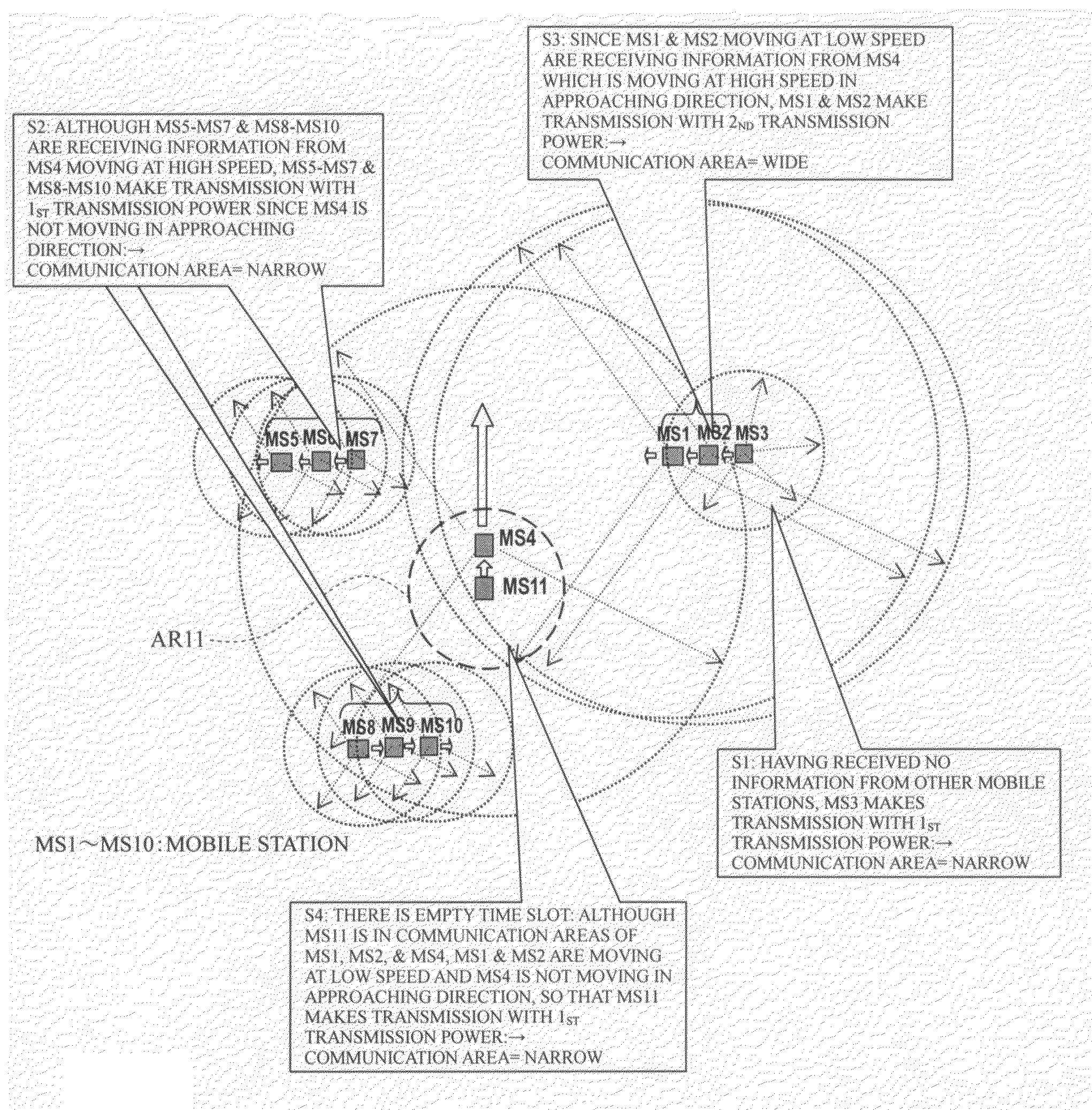
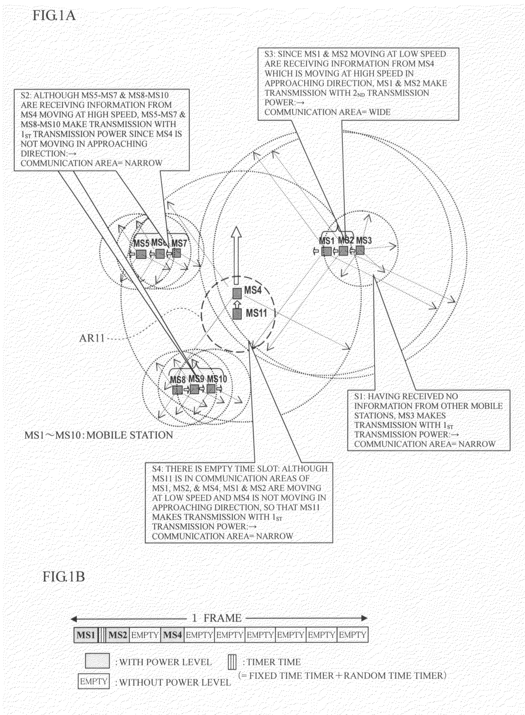
[0026]Thus, in the present invention, each mobile station controls a transmission output of its own by the “mobile speed information”, forms a communication area according to its own status, and stores the “moving speed information” and the “moving direction information” in transmission data to be transmitted. Also, each mobile station detects the “moving speed information” and the “moving direction information” from received data from another mobile station which has been received in a time zone during which its own station is not making data transmission. When the value of “moving speed information” is higher than a preset threshold, and only when the “moving direction information” detected indicates the approaching direction for the traveling direction of its own, the communication area is enlarged, thereby enabling a packet occupancy per unit time to be reduced and the minimum communication area to be formed. Thus, it is possible to further increase efficiency of a CSMA method broadcast communication which can also avoid the data collision of mobile stations.
[0027]Since it is enough to transmit information of its own station to another mobile station close to its own station when the moving speed of its own station is low, data transmission is made with a transmission power proportional to the moving speed of its own station, so that an optimum communication range according to the moving speed can be secured.
[0028]Also, when another mobile station is moving at a high speed in approaching direction even if its own mobile station is moving at a low speed, the communication area according to the moving speed of the other mobile station is secured in order to avoid a collision between the mobile stations by informing the existence of its own station to the other station. Thus, regardless of the moving speed of its own station, the transmission power can be increased, the communication range is expanded, and a proper communication area can be formed.
[0029]Accordingly, when all of the mobile stations make transmission with the same power, each of the mobile stations forms the communication area required even if too many mobile stations exist in the communication area. Therefore, an extra signal is not transmitted far, and a vacant hour is easily found even if a carrier sense is performed, which contributes to an efficient broadcast communication using the CSMA method.

Problems solved by technology

However, when the communication according to the above-mentioned CSMA method is performed and each moving speed of the mobile stations within the same communication area is low, numerous mobile stations will concurrently exist in a single communication area.
Eventually, a collision between the mobile stations is induced.
Accordingly, there is a possibility that a collision between the mobile stations may be induced.

Method used


Image

  • Transmission control method and device
  • Transmission control method and device
  • Transmission control method and device

Examples


Embodiment Construction

Arrangement of Embodiment: FIG. 2

[0040]FIG. 2 shows an arrangement of each mobile station realizing a transmission control method and device according to the present invention, which is composed of a transmission processor 100, a reception processor, and a power control processor 300 briefly.

[0041]The transmission processor 100 is composed of a location information-acquiring portion 4 of its own station, a moving direction information-acquiring portion 5 of its own station, a moving speed information-acquiring portion 6 of its own station, a transmission data generator 1 which inputs information 102-104 acquired by the information-acquiring portions 4-6 and generates transmission data 117, a modulator 2 which modulates the data 117 generated by the transmission data generator 1, a transmitting portion 3 which amplifies the power of modulation data 118 outputted from the modulator 2 and which transmits the amplified data through a directional coupler DC and an antenna ANT, a CSMA con...


PUM


Abstract

When information of its own station is transmitted to another mobile station by a CSMA access method, by a transmission control method and device, moving speed information and location information is transmitted with a predetermined minimum transmission power until a moving speed of its own station exceeds a first threshold, and the moving speed information and the location information is transmitted with a first transmission power proportional to the moving speed when the moving speed of its own station exceeds the first threshold. In this case, moving direction information of its own station may be acquired and transmitted in addition to the moving speed information and the location information. If the moving speed of the other mobile station exceeds a second threshold higher than the first threshold and a moving direction of the other mobile station is an approaching direction to its own station while its own station is not making transmission with the moving speed of its own station exceeding the first threshold, the first transmission power is switched over to a second transmission power proportional to the moving speed of the other mobile station and the moving speed information and the moving direction information is transmitted.

Description

BACKGROUND OF THE INVENTION[0001]1. Field of the Invention[0002]The present invention relates to a transmission control method and device, and in particular to a transmission control method and device in mobile stations which mutually notify their own information by using a CSMA method without interposition of a master station in order to prevent a collision between the mobile stations.[0003]2. Description of the Related Art[0004]When communication is performed by the CSMA method, a mobile station has performed a carrier sense before making data transmissions, thereby confirming whether or not data from other mobile stations exists in the air to make data transmissions of its own station when determining that no data from other mobile stations exists. The transmissions have been made with the same power enough to cover a communication area determined as a system for all of the mobile stations.[0005]While there are some CSMA methods, one example of them will now be described referrin...

Claims


Application Information

Patent Timeline
IPC IPC(8): H04Q7/20H04W24/00H04W52/28H04W52/36H04W64/00H04W74/08H04W92/18
CPCH04W4/023H04W4/027H04W24/00H04W52/28H04W52/282H04W92/18H04W52/362H04W52/367H04W64/006H04W76/023H04W52/283H04W76/14H04W74/0808
Inventor MURAKAMI, HIROKAZU
Owner FUJITSU LTD
Learn More