Electric lamp and manufacture method therefor

Inactive Publication Date: 2015-07-09
SIGNIFY HLDG BV
View PDF2 Cites 2 Cited by
  • Summary
  • Abstract
  • Description
  • Claims
  • Application Information

AI Technical Summary

Benefits of technology

The invention provides a high pressure gas discharge lamp with a UV-enhancer that improves ignition reliability. The UV-enhancer is directly adjacent to the discharge vessel, eliminating the need for a separate mounting construction. The lamp is compact and has a reduced number of components. The UV-enhancer is made of densely sintered polycrystalline Al2O3, which is widely used for high-pressure discharge lamps. The UV-enhancer is opaque due to the inclusions of ambient gas during the final sinter step, which gas is trapped inside the wall portion of the UV-enhancer. The opaque wall portion reflects the generated UV-radiation towards and into the container wall and into the discharge space during operation of the lamp, thus inducing a fast and reliable ignition of the lamp. The container wall has an outer container surface and the wall portion has an outer wall surface, and an active antenna extends over both surfaces. The separation into two parts enables a fast and reliable manufacture process. The method is simple and the resulting lamp is reliable and efficient.

Problems solved by technology

A known problem of this type of lamp is the comparatively wide spread in ignition time.
This points to a shortage of free electrons during lamp ignition.
A disadvantage of this, however, is that 85Kr is radioactive.
Disadvantages of the known lamp are the relatively complicated construction, and the relatively cumbersome manufacture process which, in addition, is relatively expensive.

Method used


Image

  • Electric lamp and manufacture method therefor
  • Electric lamp and manufacture method therefor
  • Electric lamp and manufacture method therefor

Examples


Embodiment Construction

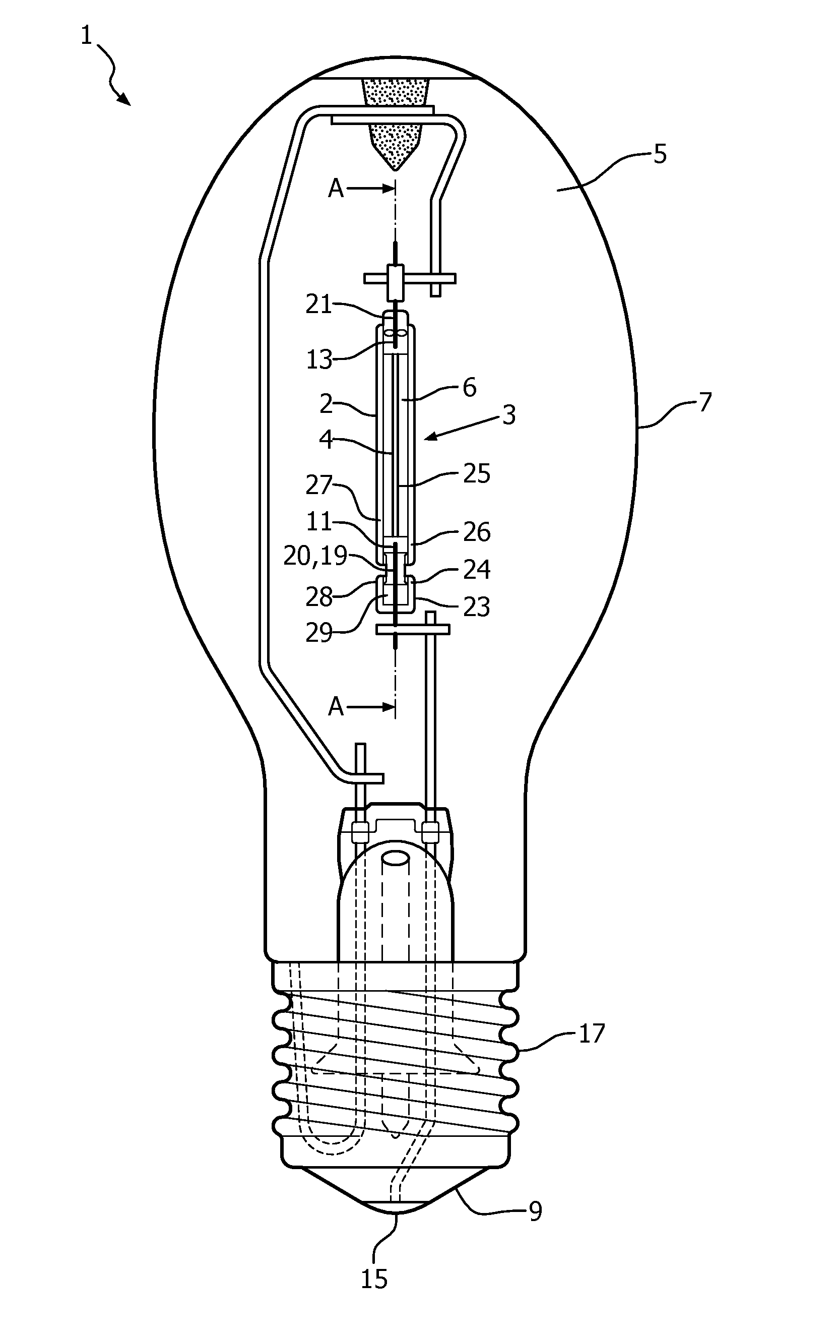
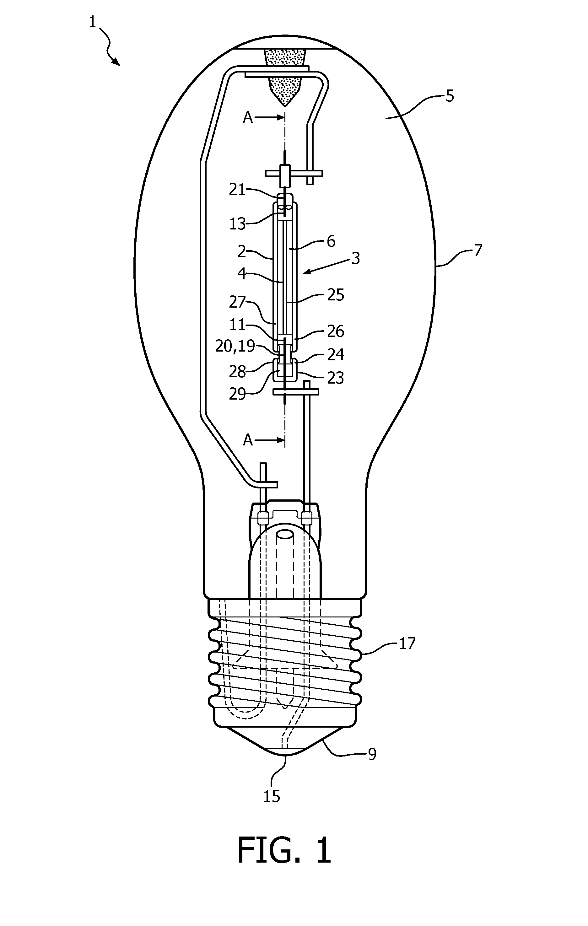
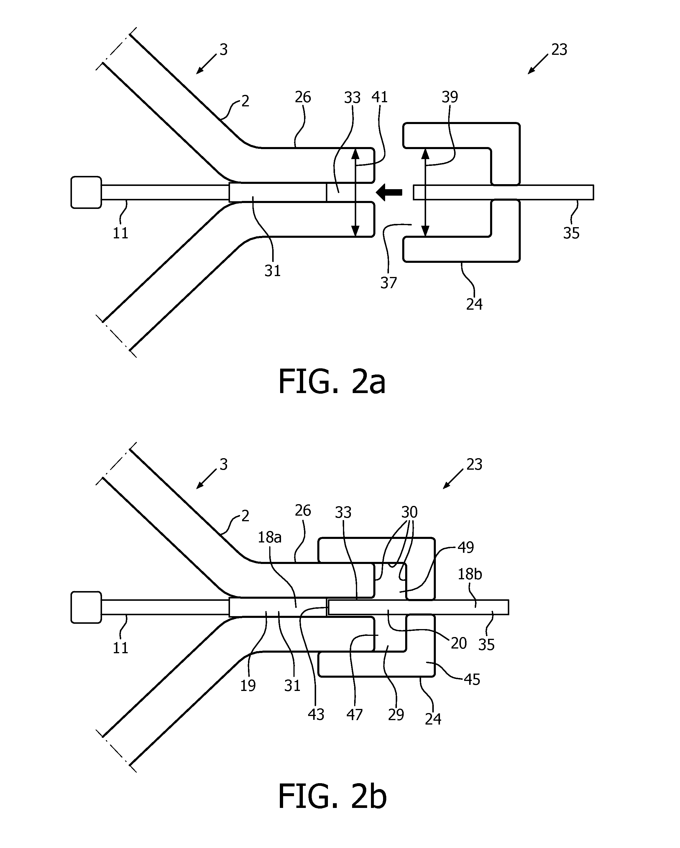
[0030]FIG. 1 shows a high-pressure metal halide lamp 1 comprising a discharge vessel 3 having a container wall 2 enclosing a discharge space 4 filled with a filling 6, which discharge vessel 3 is surrounded, with an interspace 5, by an outer envelope 7, which supports a lamp cap 9. The discharge vessel 3 is made of densely sintered polycrystalline aluminum oxide and has a first lamp electrode 11 and a second lamp electrode 13, which electrodes are connected to respective contacts 15 and 17 on the lamp cap 4 by means of a respective first 19 and second feedthrough 21, extending over a longitudinal axis A of the discharge vessel 3. The lamp 1 is provided with an UV enhancer 23 having a wall portion 24, said UV-enhancer 23 is situated at an end part 26 of the discharge vessel 3. The UV enhancer 23 has the first feedthrough 19 as an internal enhancer electrode 20. The UV enhancer 23 has a capacitive coupling with an antenna 25 extending over an outer container surface 27 of the containe...


PUM


Abstract

A high pressure gas discharge lamp (1) which comprises a ceramic discharge vessel (3) having a container wall (2) enclosing a discharge space (4) having a filling (6). A first (11) and a second electrode (13) are mutually oppositely arranged in the discharge space and are mounted on a first (19) and a second feed-through (21) respectively, which extend in a gas-tightly sealed manner through the container wall (2). A UV-enhancer (23) comprises a wall portion (24) and a chamber (29), said chamber being enclosed by the wall portion (24) of the UV-enhancer (23) and an end part (26) of the container wall (2).

Description

BACKGROUND OF THE INVENTION[0001]The invention relates to a high pressure gas discharge lamp comprising a ceramic discharge vessel having a container wall enclosing a discharge space having a filling, further comprising a first and a second electrode, mutually oppositely arranged in the discharge space and defining a length axis of the discharge vessel, still further comprising a first and a second feedthrough, both extending in a gas-tightly sealed manner through the container wall and on which feedthroughs a respective electrode is mounted, and further comprising a UV-enhancer.[0002]The invention further relates to a method of manufacture of said electric lamp. A lamp of the type mentioned in the opening paragraph is known from U.S. Pat. No. 5,811,933. The known lamp is a high-pressure discharge lamp, more in particular a metal halide lamp. Such a lamp is suitable for various applications such as general interior lighting, general exterior lighting, video illumination, etc. The di...

Claims


Application Information

Patent Timeline
IPC IPC(8): H01J61/54H01J61/34H01J9/24H01J61/82
CPCH01J61/547H01J9/247H01J61/34H01J61/827H01J61/54
Inventor BLEES, MARTIN HILLEBRAND
Owner SIGNIFY HLDG BV
Why Eureka
Try Eureka