
Energy protection device for an aircraft

Active Publication Date: 2015-07-09
AIRBUS OPERATIONS SAS
View PDF3 Cites 4 Cited by
  • Summary
  • Abstract
  • Description
  • Claims
  • Application Information

AI Technical Summary

Benefits of technology

The invention is about a method for protecting the energy of an aircraft during a flight. The method is particularly useful in situations where the aircraft needs to perform a maximum thrust maneuver. The method automatically deactivates the energy protection function only when certain conditions are met, such as a relaxing of the control member and a certain angle of attack. This prevents the energy protection function from being deactivated when the aircraft is still in a protected state. By detecting and controlling these conditions, the method ensures that the aircraft can perform a maximum thrust maneuver without needing the energy protection function.

Problems solved by technology

However, there are situations which require a maximum engine thrust to be maintained, even if the conditions of engagement of the protection function are no longer fulfilled.
Thus, the drawback of a device configured to trigger then automatically deactivate an energy protection mode as a function of flight parameters is the risk of exiting from this mode at the time of an avoidance maneuver.

Method used


Image

  • Energy protection device for an aircraft
  • Energy protection device for an aircraft

Examples


Embodiment Construction

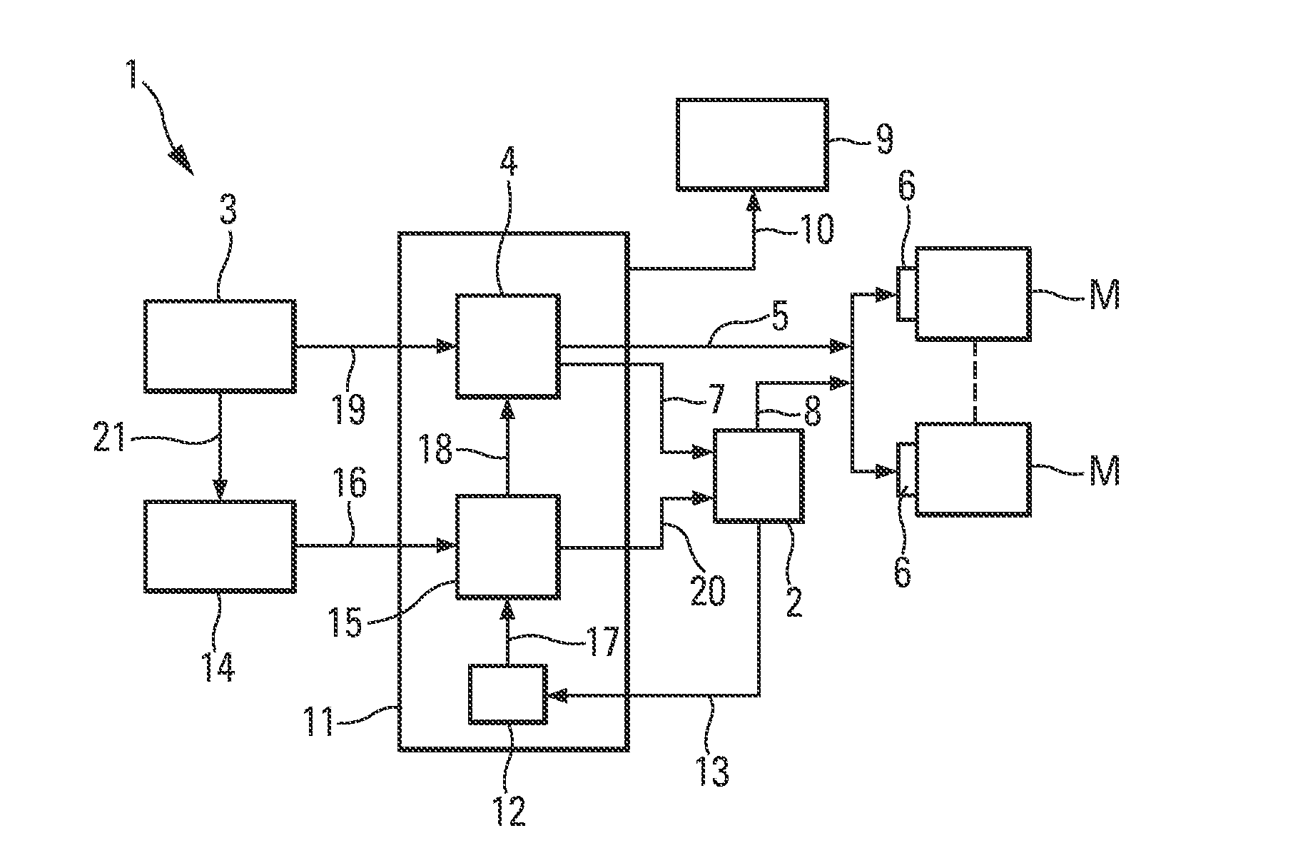
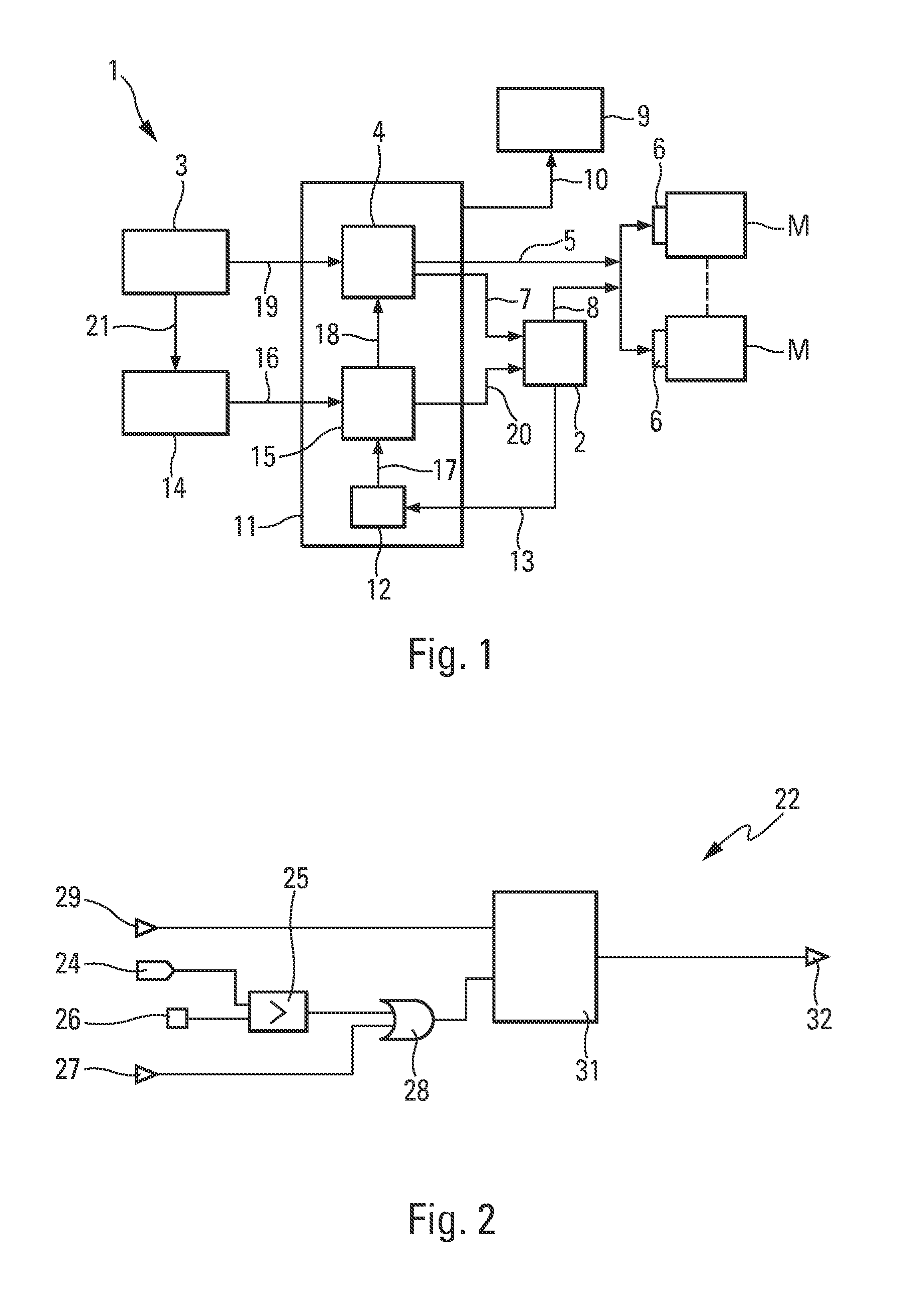
[0044]The device 1 illustrating an embodiment of the invention and schematically represented in FIG. 1 is an energy protection device for an aircraft (not represented), in particular a transport airplane, which is provided with at least one, but preferably a plurality, of usual engines M, as well as an autothrust 2 and a piloting control member (not represented), such as a control stick.

[0045]This device 1 comprises, to this end, means specified hereinbelow, which make it possible to protect the aircraft against low-energy situations (low speed, high angle of attack, low engine thrust) likely to constitute a hazard for safety, notably close to the ground.

[0046]For this, said device 1 is of the usual type comprising:[0047]a monitoring unit 3 configured to automatically and repetitively monitor, during a flight of the aircraft, a plurality of data of said aircraft, including the angle of attack, so as to be able to detect, in the usual manner, a trigger situation, for which conditions...


PUM


Abstract

Energy protection device for an aircraft.The device (1) comprises units (12, 14, 15) for automatically deactivating an energy protection function, if a return of the aircraft to an operational flight domain is detected after the activation of this protection function, and for automatically managing an autothrust (2), if at least one of the following conditions is satisfied: a relaxing of a control member is detected, and the angle of attack of the aircraft is below a predetermined threshold.

Description

[0001]The present invention relates to an energy protection device for an aircraft, notably a transport airplane.[0002]More specifically, said device is intended to protect the aircraft against low energy situations (low speed, high angle of attack, low engine thrust), notably close to the ground.BACKGROUND OF THE INVENTION[0003]Generally, such a device usually comprises:[0004]means for automatically and repetitively monitoring, during a flight of the aircraft, a plurality of aircraft data so as to be able to detect a low energy situation, for which conditions relating to a low energy are satisfied; and[0005]means for automatically activating, if such a low energy situation is detected, a protection function consisting in automatically engaging an autothrust and in automatically controlling the engines of the aircraft so that they supply a maximum thrust.[0006]The protection function which is defined in the flight guidance and control computers of the aircraft therefore generates, i...

Claims


Application Information

Patent Timeline
IPC IPC(8): B64D31/06
CPCB64D31/06B64C13/506
Inventor MOUNE, MARIE-CLAIREMULLER, JEANPOUJOL, CHRISTOPHEFONTAN, JULIEN
Owner AIRBUS OPERATIONS SAS
Learn More