
Wireless power supply system

a power supply system and wireless technology, applied in the direction of batteries, exchanging data chargers, inductances, etc., can solve problems such as power declin

Inactive Publication Date: 2015-07-02
CANON KK
View PDF4 Cites 83 Cited by
  • Summary
  • Abstract
  • Description
  • Claims
  • Application Information

AI Technical Summary

Benefits of technology

The present invention is about preventing a power receiving device from receiving too much power from multiple power transmitting devices simultaneously. The invention assigns a power receiving device to a specific power transmitting device and determines a schedule for supplying power to the device to avoid overloading. This helps to prolong the life of the power receiving device and ensures more efficient power use.

Problems solved by technology

However, in the case that the plurality of power transmitting apparatuses of the same power transmitting frequency are present, a problem arises that receiving power declines since interference occurs among electromagnetic waves output from the individual power transmitting apparatuses when the power receiving apparatus simultaneously receives wireless power supply from the plurality of power transmitting apparatuses.

Method used


Image

  • Wireless power supply system
  • Wireless power supply system
  • Wireless power supply system

Examples


embodiment 1

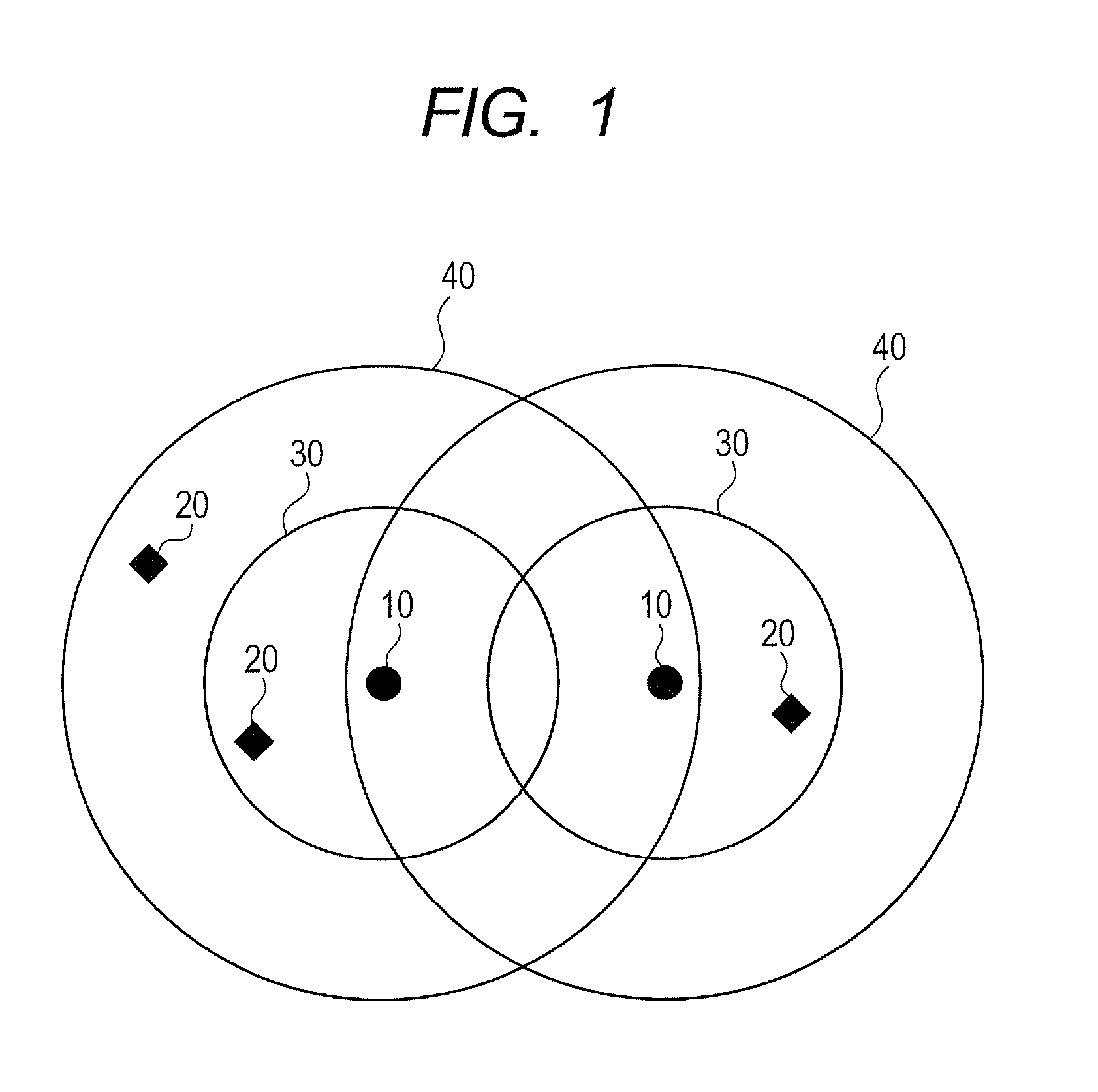
[0041]FIG. 1 is a conceptual diagram illustrating one example of a configuration of an N-to-N wireless power supply system in which a plurality of power transmitting apparatuses transmit power to a plurality of wireless power receiving apparatuses.

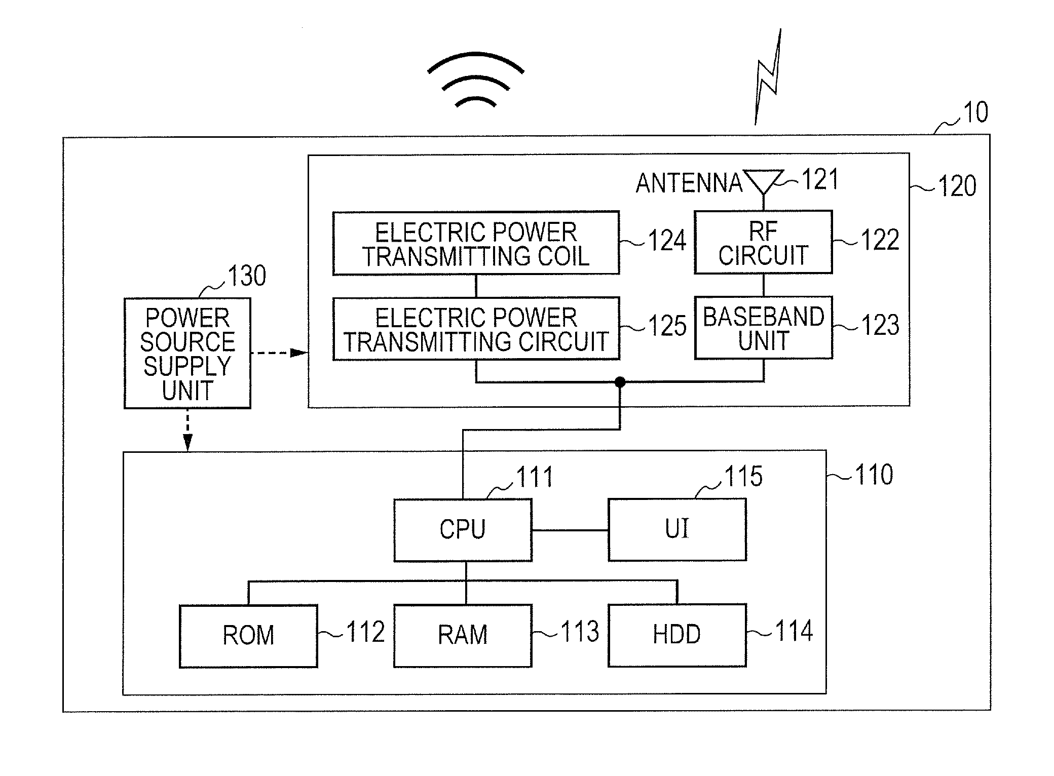
[0042]A power transmitting apparatus 10 wirelessly transmits the power to a power receiving apparatus 20. Also, the power transmitting apparatus 10 performs data communication required for power supply with the power receiving apparatus 20.

[0043]The power receiving apparatus 20 wirelessly receives the power from the power transmitting apparatus 10. Also, the power receiving apparatus 20 performs the data communication required for the power supply with the power transmitting apparatus 10.

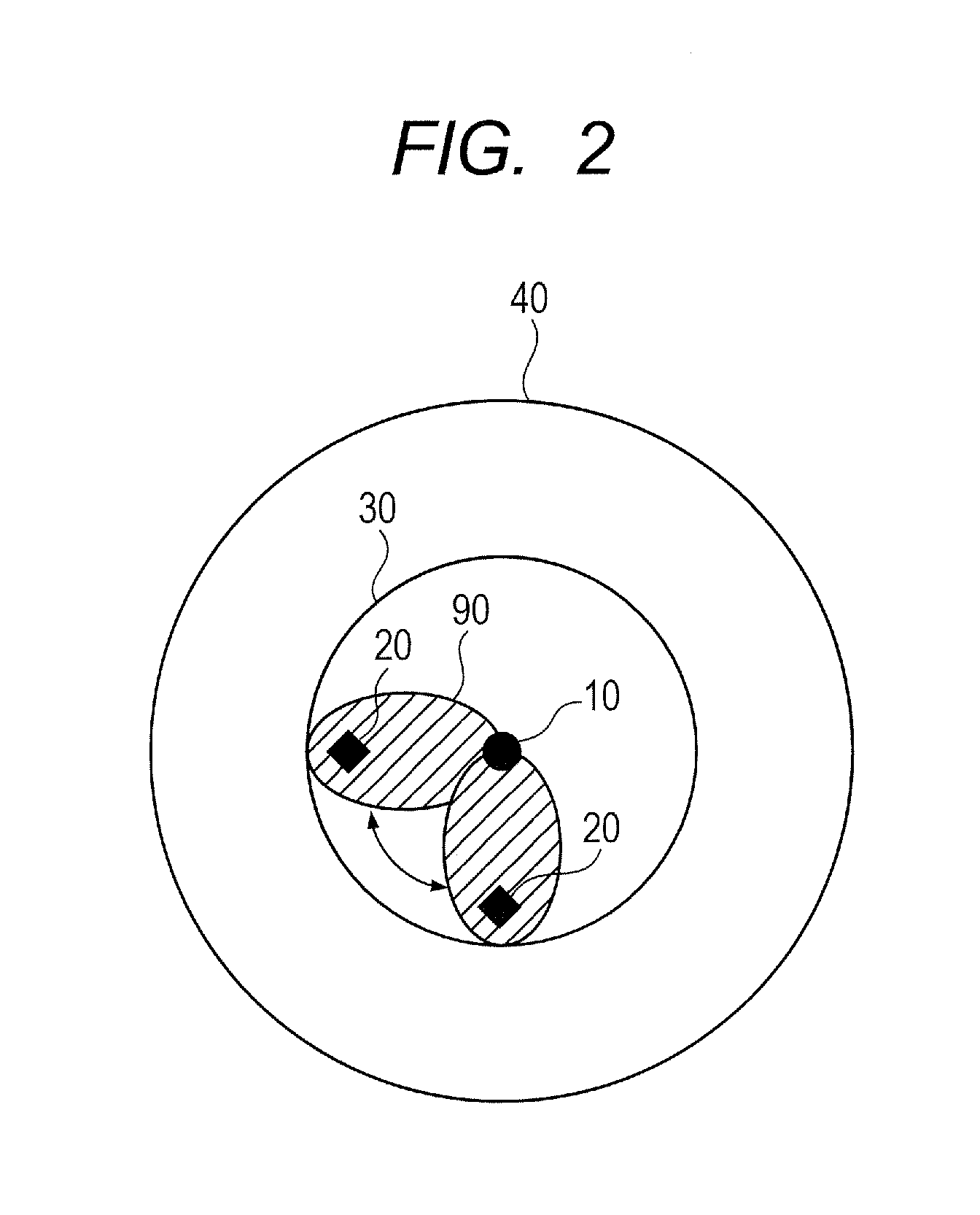
[0044]A power supply area 30 is an area where the power supply can be executed from the power transmitting apparatus 10 to the power receiving apparatus 20. However, the power transmitting apparatus 10 cannot simultaneously supply the power to the entire p...

embodiment 2

[0197]In the embodiment 1, when the master power transmitting apparatus BSM10 determines the time-sharing power supply schedule, it is taken into consideration only that adjustment is executed so as not to simultaneously supply the power to the same power receiving apparatus from the plurality of power transmitting apparatuses BSM10 and BSS11. Therefore, the master power transmitting apparatus BSM10 defines that the time (the number of cycles) during which the individual power transmitting apparatuses BSM10 and BSS11 supply the power to the plurality of power receiving apparatuses is the same, and determines the time-sharing power supply schedule. Accordingly, for the power receiving apparatus DSC22 supplied with the power from both of the master power transmitting apparatus BSM10 and the slave power transmitting apparatus BSS11, power receiving time is about twice as long as the power receiving time of the other power receiving apparatuses DSB21 and DSD23. As a result, a difference...


PUM

PropertyMeasurementUnit
timeaaaaaaaaaa
poweraaaaaaaaaa
timeaaaaaaaaaa

Abstract

In a wireless power supply system, a power transmitting apparatus wirelessly supplies power to an assigned power receiving apparatus. The wireless power supply system includes an assigning unit that assigns the power receiving apparatus to the power transmitting apparatus, and a determining unit that, when the assigning unit assigns a particular power receiving apparatus to a plurality of power transmitting apparatuses, determines a power supply schedule such that the plurality of power transmitting apparatuses supply the power to the particular power receiving apparatus, not simultaneously.

Description

BACKGROUND OF THE INVENTION[0001]1. Field of the Invention[0002]The present invention relates to a wireless power supply system in which a power transmitting apparatus wirelessly supplies power to a power receiving apparatus assigned.[0003]2. Description of the Related Art[0004]Four systems are known as a system of supplying power contactlessly (wirelessly). Specifically, they are an electromagnetic induction system, a magnetic field resonance system, an electronic filed coupling system and a radio wave reception system. In recent years, among the four systems, the magnetic field resonance system capable of compatibly achieving sufficient power that can be transmitted and a long power transmitting distance is drawing attention. In the magnetic field resonance system, a one-to-N power supply system in which a power transmitting apparatus transmits the power to a plurality of power receiving apparatuses utilizing the power transmitting distance is proposed (for instance, Japanese Pate...

Claims


Application Information

Patent Timeline
Patent Type & Authority Applications(United States)
IPC IPC(8): H01F38/14H02J5/00H04B5/48
CPCH02J5/005H01F38/14H02J1/14H02J7/00045H02J7/00034H02J50/402H02J50/20H02J50/10H02J2310/66H02J50/80
Inventor YANAGAWA, KATSUHIKO
Owner CANON KK
Learn More