
Imaging device, and focus-confirmation display method

a display method and imaging device technology, applied in the field of imaging devices and focus confirmation display methods, can solve the problems of increasing the number of components, difficult to achieve, and the user cannot accurately adjust the focus by manual focusing, so as to facilitate the pre-operation of manual focus operation

Active Publication Date: 2015-07-02
FUJIFILM CORP
View PDF22 Cites 16 Cited by
  • Summary
  • Abstract
  • Description
  • Claims
  • Application Information

AI Technical Summary

Benefits of technology

The present invention provides an imaging device and a focus-confirmation display method that make it easy for users to manually focus without changing the position, size, or direction of the image or the boundary line between image divisions. This technology makes it simpler for users to achieve precise focus and improves the overall quality of the captured images.

Problems solved by technology

However, since the digital camera described in PTL 1 requires a mechanical configuration for moving an aperture, there is a problem of securing a space for storing the configuration and a problem of increase in the number of components.
In addition, since the digital camera described in PTL 2 includes no configuration in which pupil-split is applied to subject light beams to take an image, it is difficult to achieve a focus-confirmation image (split image) that is accurate and has no failure.
Thus, if a split line exists in a position different from a position to be in focus, a user cannot accurately adjust focus by manual focusing.
Although the digital camera described in PTL 5 changes a position of each of images in a split image, there is a problem in which if a position of each of the images in the split image is changed after a photographer sets a field angle so that an image of a subject to be in focus by manual focusing fits within a display area of the split image, the photographer is embarrassed.
In addition, according to the digital camera described in PTL 5, directions (horizontal and vertical split directions) of a split line are changed, however, there is a problem in which if a direction of the split line is suddenly changed in the vertical direction when a photographer manually operates the digital camera so as to eliminate deviation in the horizontal direction during focusing by manual focusing, for example, the photographer is embarrassed.

Method used


Image

  • Imaging device, and focus-confirmation display method
  • Imaging device, and focus-confirmation display method
  • Imaging device, and focus-confirmation display method

Examples


third embodiment

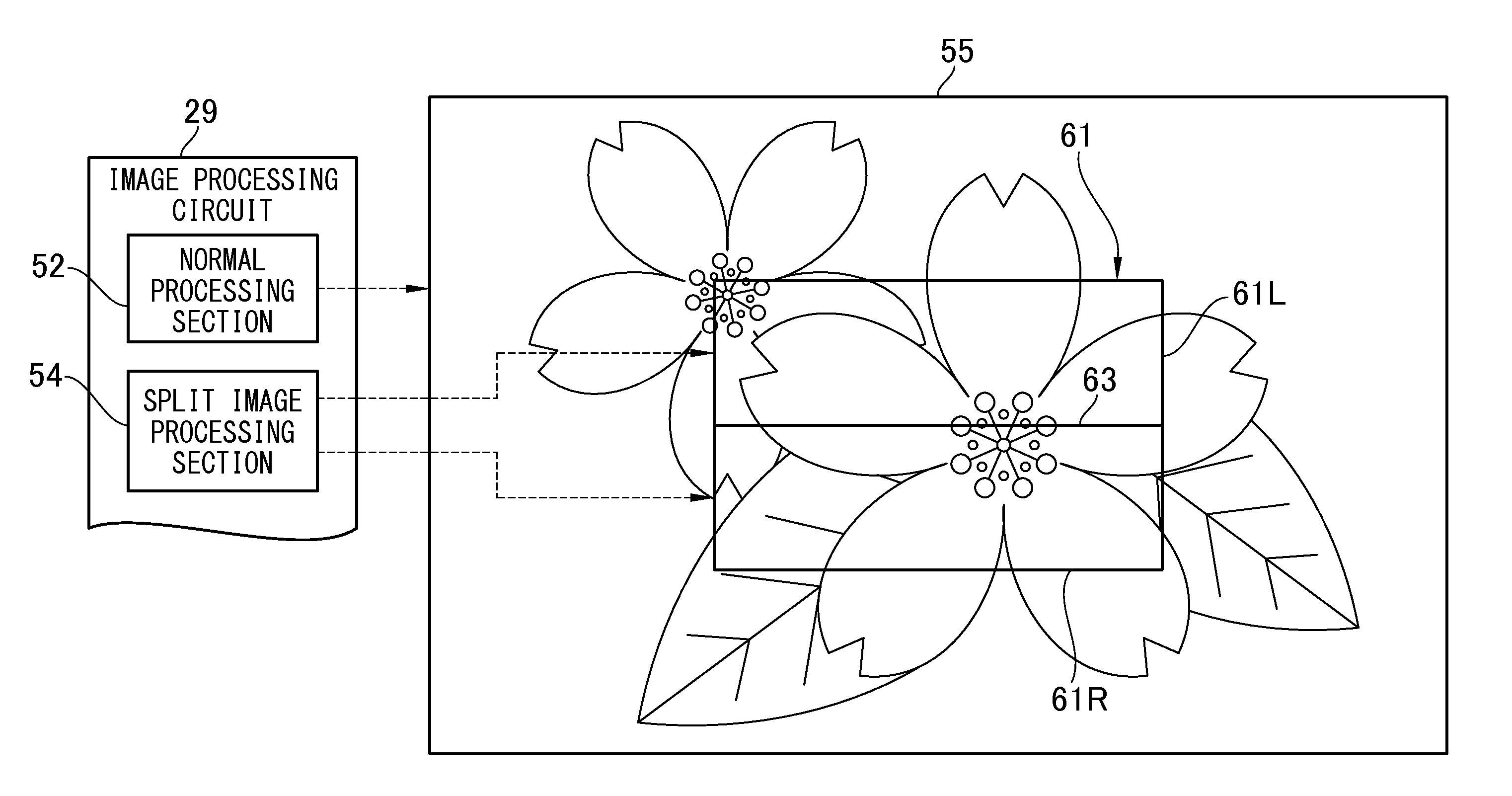
[0185]In the digital camera 2 of a third embodiment, in a case where the number of the split lines 63 (boundary line) inputted by manual operation is indicated as L, the selection control section (designated by reference numeral 106 in FIG. 6) allows the operation section 9 (number input device) to accept only the L of an odd number, and to position the split line 63 in a place of (L+1) / 2 of the number L of the split lines 63 at the center or near the center of the split image 61 (focus-confirmation image).

[0186]Here, “near the center” means a position from the center of the split image 61 within ±5% of an overall width of the split image 61 in the vertical direction V, for example.

[0187](Example of Focus-Confirmation Image Display Processing of Third Embodiment)

[0188]FIG. 18 is a flow chart showing a flow of an example of focus-confirmation image display processing in the third embodiment. The present processing is performed by control of the CPU 11 constituting the selection contr...

fourth embodiment

[0197]In the digital camera 2 of a fourth embodiment, the selection control section (designated by reference numeral 106 in FIG. 6) changes a position of the split line 63 (boundary line) in the split image 61 (focus-confirmation image) as time elapses.

[0198](Example of Focus-Confirmation Image Display Processing of Fourth Embodiment)

[0199]FIG. 19 is a flow chart showing a flow of an example of focus-confirmation image display processing in the fourth embodiment. The present processing is performed by control of the CPU 11 constituting the selection control section 106 in accordance with a program. First, the number of the split lines 63 (the number of lines) of the first image 58a and the second image 58b is set at “N” (step S402). Next, a time interval T of changing the split line 63 is calculated (step S404). In the present example, T=1 / N is calculated on the basis of the number N of the lines.

[0200]Subsequently, a position of the split line 63 in the split image 61 is changed as...


PUM


Abstract

The present invention provide an imaging device that includes an image generation device, a boundary change device configured to change a position of a boundary between the first image and the second image in the second image for display, in a direction orthogonal to the boundary, a selection device configured to select any one of the first image and the second image for each of a plurality of divisions in the second image for display, divided by the boundary changed by the boundary change device, a display device, and a display control device configured to allow the display device to display the first image for display, and allows the second image for display in which a position of the boundary is changed by the boundary change device to be displayed in a display area in the first image for display.

Description

CROSS-REFERENCE TO RELATED APPLICATIONS[0001]This application is a Continuation of PCT International Application No. PCT / JP2013 / 074832 filed on Sep. 13, 2013, which claims priority under 35 U.S.C §119(a) to Japanese Patent Application No. 2012-206214 filed on Sep. 19, 2012. Each of the above application(s) is hereby expressly incorporated by reference, in its entirety, into the present application.BACKGROUND OF THE INVENTION[0002]1. Field of the Invention[0003]The present invention relates to an imaging device and a focus-confirmation display method that display an image (hereinafter also referred to as a “split image”) to be used for focus-confirmation during manual focusing.[0004]2. Description of the Related Art[0005]There is a well-known digital camera provided with an autofocus function using a phase difference detection method or a contrast detection method along with a so-called manual focus mode in which a user can manually adjust focus. There is a well-known digital camera ...

Claims


Application Information

Patent Timeline
Patent Type & Authority Applications(United States)
IPC IPC(8): G03B13/28H04N5/232
CPCG03B13/28H04N5/23293H04N5/23212G02B7/34G03B13/36G03B17/18H04N23/672H04N23/62H04N23/611H04N23/667H04N23/633H04N23/632H04N25/704H04N23/843H04N25/134
Inventor KAWAI, TOMOYUKIIWASAKI, YOICHIINOUE, KAZUKIKOGUCHI, TAKEHIRO
Owner FUJIFILM CORP
Learn More