Eureka AIR delivers breakthrough ideas for toughest innovation challenges, trusted by R&D personnel around the world.

Welder With Active Linear DC Filtering Circuit

a filtering circuit and welder technology, applied in the field of welding, can solve the problems of inconvenient use, high energy output of purpose welders, inconvenient operation, etc., and achieve the effect of improving the efficiency of the welder, improving the efficiency and improving the quality of the welding process

Inactive Publication Date: 2015-06-25
ASTLE AARON +3
View PDF0 Cites 6 Cited by
  • Summary
  • Abstract
  • Description
  • Claims
  • Application Information

AI Technical Summary

Benefits of technology

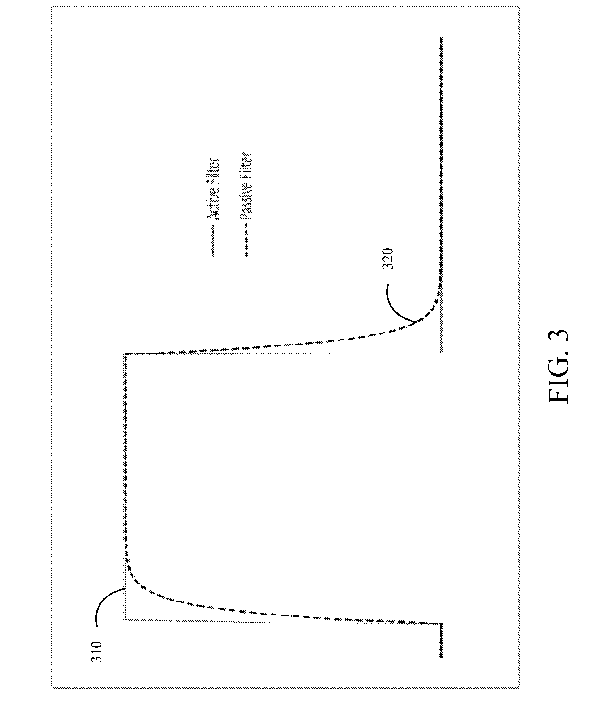
This patent is about a new invention that helps create different waveforms. The text explains that the timing, energy, and voltage levels shown in the figures are not exact, but are meant to show the qualitative effects of the invention. The variations in waveforms produced by the invention may be exaggerated to highlight the important features and results. Overall, the patent aims to provide a better understanding of the invention's capabilities and how it can be used to create new waveform patterns.

Problems solved by technology

Unfortunately, since a CD power supply is open loop with no feedback, changes in the secondary circuit, such as loose cables or corroded connections can result in inconsistent energy delivery to the parts.
AC power supplies are general purpose welders with high energy output and are generally not suitable for critical, fine welding applications.
When using commonly known CD welding systems in certain welding processes (e.g. thermocompression bonding) it is quite common to experience a large number of failures caused by weak bonds.
Conversely, using a DC welding system for the same application can provide good joint strength but may be cost prohibitive due to the relatively high cost of a DC welding system suitable for the application.
However, both of these benefits can become limitations in different applications.
Because the system uses a stored energy method, the weld time is limited by the amount of stored energy available.
Also, because the slope or decay rate is an intrinsic physical characteristic of the devices used to create the storage device, it is a static parameter that cannot be readily adjusted or controlled.
The main drawback to the DC power supply is that it can be quite difficult to generate high peak output currents since the energy is generated and supplied from the DC power supply in real time during the welding and is not easily stored.
By extension, the development and manufacture of a high current DC power supply that can achieve similar peak weld currents to the traditional CD welder is very costly.
The higher power characteristics of this type of power supply will also increase the likelihood of power supply failure.
Additionally, CD welder power supplies can also can achieve very high peak weld currents for short amounts of time but the weld current decay rate is a function of system capacitance and weld system resistance, which may be limiting.

Method used


Image

  • Welder With Active Linear DC Filtering Circuit
  • Welder With Active Linear DC Filtering Circuit
  • Welder With Active Linear DC Filtering Circuit

Examples


Embodiment Construction

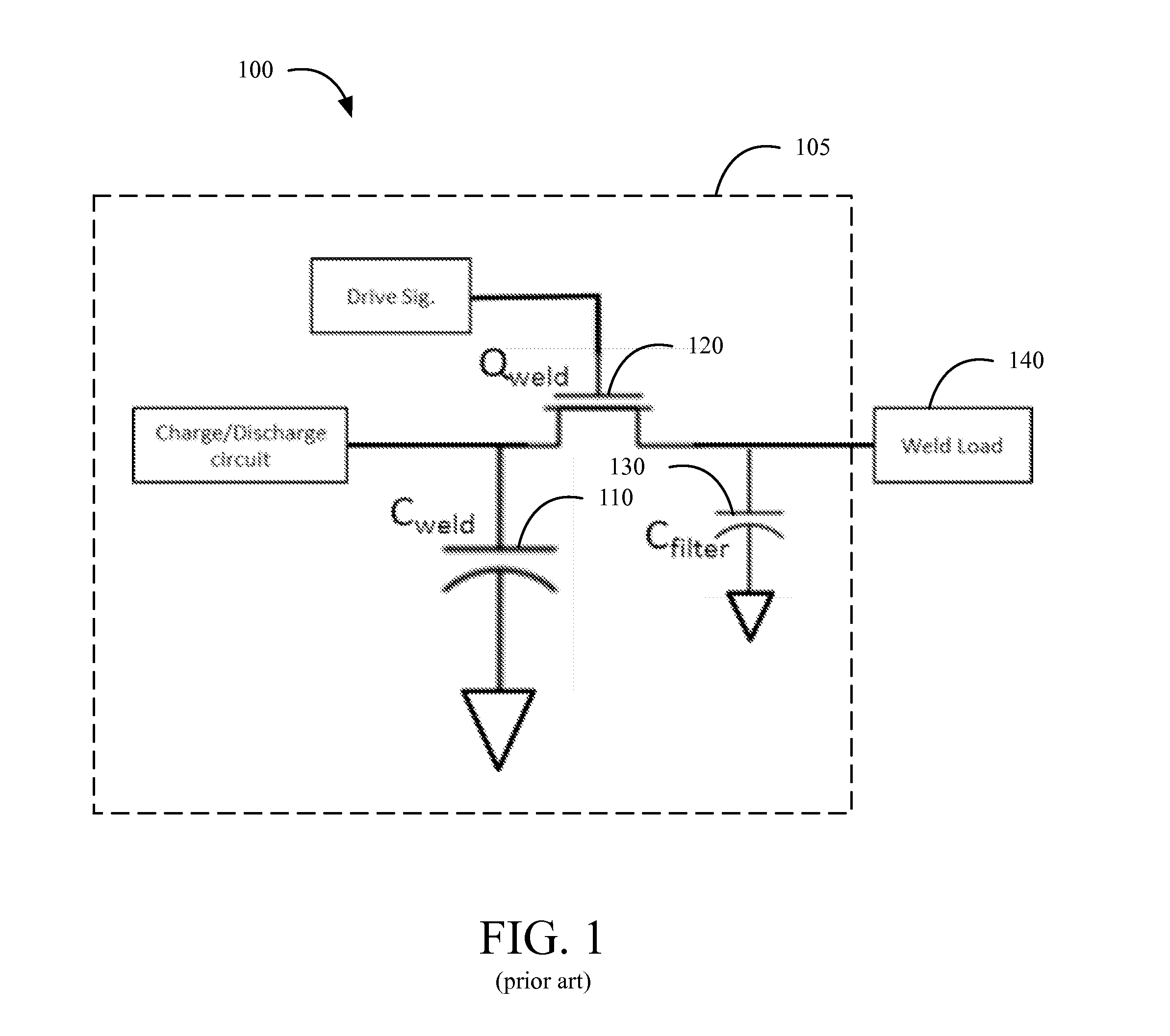
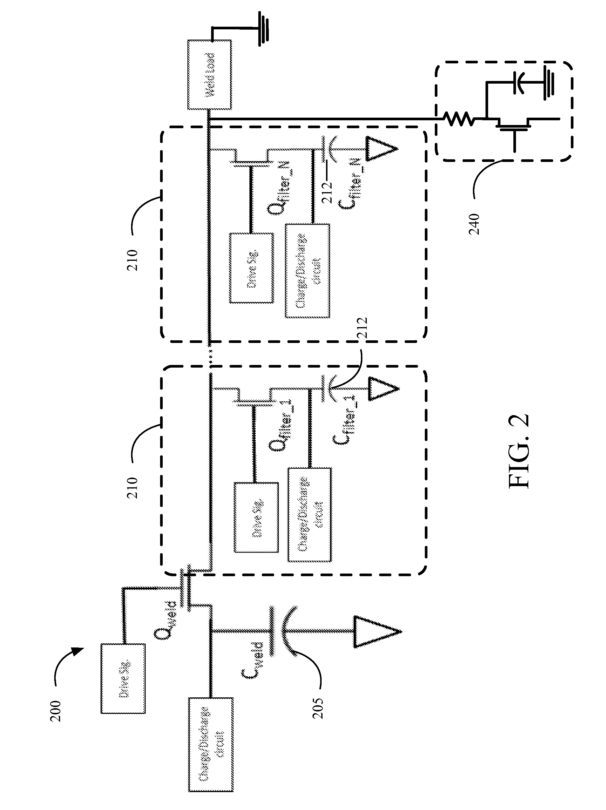
[0039]A linear DC welder for enhanced welding capabilities comprises one or more active filtering circuits. The active filtering circuit(s) are capable of producing a variety of user-configurable and user-controllable custom waveforms for use in various welding applications. The custom waveforms may be created and combined via the use of overlay waveforms and, in at least some preferred embodiments of the present invention, include agitation waveforms. The overall operation of the welder, including the power supply and the active filtering circuit can be controlled via an integrated feedback cycle that provides for the monitoring and adjustment of multiple weld process parameters including volts, amps, power, resistance, and displacement. Additionally, a low current ignition (“LCI”) circuit may also be included to provide for additional welding options.

[0040]The most preferred embodiments of the present invention are configured to deliver both capacitive discharge energy and control...


PUM

PropertyMeasurementUnit
Electrical resistanceaaaaaaaaaa
Currentaaaaaaaaaa
Electric potential / voltageaaaaaaaaaa

Abstract

A linear DC welder for enhanced welding capabilities comprises one or more active filtering circuits. The active filtering circuit(s) are capable of producing a variety of user-configurable and user-controllable custom waveforms for use in various welding applications. The custom waveforms may be created and combined via the use of overlay waveforms and, in at least some preferred embodiments of the present invention, include agitation waveforms. The overall operation of the welder, including the power supply and the active filtering circuit can be controlled via an integrated feedback cycle that provides for the monitoring and adjustment of multiple weld process parameters including volts, amps, power, resistance, and displacement. Additionally, a low current ignition (“LCI”) circuit may also be included to provide for additional welding options.

Description

RELATED APPLICATIONS[0001]This patent application is a continuation-in-part of U.S. patent application Ser. No. 14 / 262,743, which application was filed on Apr. 26, 2014 and which application is currently pending and which application is incorporated herein by reference.[0002]This patent application is a continuation-in-part of U.S. patent application Ser. No. 14 / 084,575, which application was filed on Nov. 19, 2013 and which application is currently pending and which application is incorporated herein by reference.[0003]This patent application is also a continuation-in-part of U.S. patent application Ser. No. 13 / 674,022, which application was filed on Nov. 12, 2012 and which application is now pending and which application is incorporated herein by reference.BACKGROUND OF THE INVENTION[0004]1. Technical Field[0005]The present invention relates to the field of welding and more specifically relates to controlling the output from a power supply used in various welding applications.[000...

Claims


Application Information

Patent Timeline
IPC IPC(8): B23K11/24B23K10/00B23K11/26
CPCB23K11/243B23K10/006B23K11/26B23K9/1043B23K9/1081B23K9/167B23K11/241
Inventor ASTLE, AARONFORD, AARON J.PEACOCK, LUKE B.DODGEN, LARIN A.
Owner ASTLE AARON
Why Eureka
Eureka Blog
Learn More