
Thermostatic mixing valve

a technology of mixing valve and thermostat, which is applied in the direction of water installations, instruments, constructions, etc., can solve the problems of reducing the available setting range of the corresponding stroke movement of the overload unit, and the intensive arrangement of the switch and the cam ring in the thermostatic mixing valve in terms of both space and parts, so as to reduce the required installation space and parts, the available setting range is increased.

Active Publication Date: 2015-06-18
GROHE
View PDF6 Cites 10 Cited by
  • Summary
  • Abstract
  • Description
  • Claims
  • Application Information

AI Technical Summary

Benefits of technology

The present invention is about a thermostatic mixing valve that can easily adjust its settings and requires less space for installation. The valve uses a gear stage and a linear displacement element to detect its position, allowing for a wider range of settings. This means that the valve can work efficiently and can be adjusted easily to different temperature ranges.

Problems solved by technology

However, this greatly reduces the available setting range for the thermostatic mixing valve.
In addition, the arrangement of the switch and the cam ring in the thermostatic mixing valve is intensive in terms of both space and parts.
In a setting process, the adjusting nut is caused to rotate, resulting in a corresponding stroke movement of the overload unit.

Method used


Image

  • Thermostatic mixing valve
  • Thermostatic mixing valve
  • Thermostatic mixing valve

Examples


Embodiment Construction

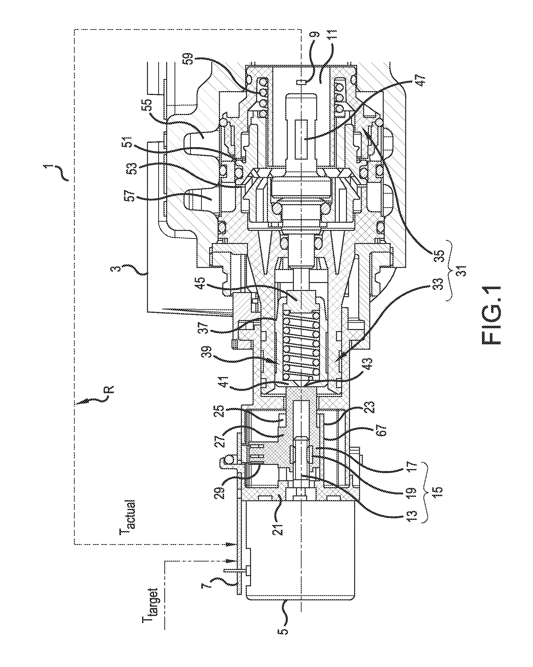
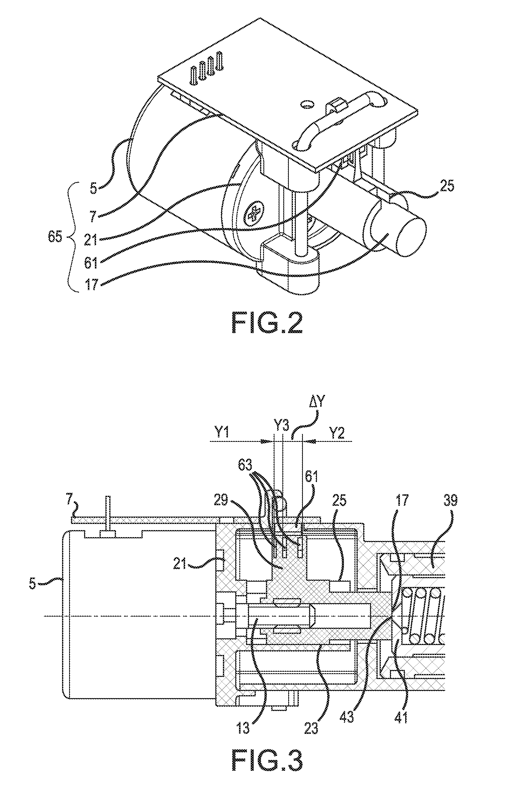
[0025]In FIG. 1, thermostatic mixing valve 1 is shown in a mounting position, namely, in a sanitary fitting 3, for instance, for a shower. Thermostatic mixing valve 1 in the present case has no operating knob for a manual setting of the mixed water temperature, but rather an electric motor 5 whose control unit 7 has a contact-free signal connection (shown by the dashed arrows in FIG. 1) with a remote control unit operable by a user. The user transmits a desired target mixed water temperature Ttarget to control unit 7 by means of the remote control unit. Control unit 7 together with electric motor 5 and temperature sensor 9, indicated in FIG. 1 and arranged in mixed water chamber 11, is integrated in a control loop R. Depending on the target mixed water temperature Ttarget, preset on the user side, via control loop R an adjustment occurs of the actual mixed water temperature Tactual detected by temperature sensor 9 to the target mixed water temperature Ttarget, preset on the user sid...


PUM


Abstract

A thermostatic mixing valve for mixing cold water and hot water and for setting a mixed water temperature, having an electric motor that is controllable by a control unit and acts via a gear stage on a valve body, which is stroke-adjustable over a setting range and with which the mixing ratio between hot and cold water can be varied depending on a target mixed water temperature, presettable on the user side, and having a sensor element for detecting at least one set position in the setting range of the thermostatic mixing valve. The gear stage has a linearly adjustable linear displacement element, arranged rotationally fixed and provided between the electric motor and the valve body, and the sensor element works together with the linear displacement element to detect the set position.

Description

[0001]This nonprovisional application claims priority under 35 U.S.C. § 119(a) to German Patent Application No. 10 2013 019 074.6, which was filed in Germany on Nov. 15, 2013, and which is herein incorporated by reference.BACKGROUND OF THE INVENTION[0002]1. Field of the Invention[0003]The present invention relates to a thermostatic mixing valve for mixing cold water and hot water and to setting the mixed water temperature.[0004]2. Description of the Background Art[0005]The structure and operating mode of such a thermostatic mixing valve is disclosed, for example, in DE 10 2006 032 018 A1, according to which the thermostatic mixing valve for setting the mixing water temperature can be built into a sanitary fitting, for instance, into a shower.[0006]DE 10 2008 058 515 A1 discloses a generic thermostatic mixing valve, in which the setting of the mixed water temperature is no longer preset manually via an operating knob by the user, but rather the thermostatic mixing valve can be contro...

Claims


Application Information

Patent Timeline
Patent Type & Authority Applications(United States)
IPC IPC(8): G05D23/13E03C1/04
CPCE03C1/04G05D23/1313G05D23/1393G05D23/1925
Inventor HUCK, KAISCHWARTPAUL, TANJAMIELKE, ACHIM
Owner GROHE
Learn More