
Method of limiting permeability of a matrix to limit liquid and gas inflow

a technology of permeability and matrix, applied in the direction of soil conditioning composition, sealing/packing, borehole/well accessories, etc., can solve the problems of leakage, flooding and/or contamination

Active Publication Date: 2015-06-18
RELBORGN +1
View PDF7 Cites 7 Cited by
  • Summary
  • Abstract
  • Description
  • Claims
  • Application Information

AI Technical Summary

Benefits of technology

The patent describes a method for controlling the setting time of a sealing composition in a passage, such as in a shaft or tunnel being excavated in a ground formation. This is achieved by adding additives to prevent setting of the composition before it reaches the designated site. Non-limiting examples of additives include coagulation or setting inhibitors, such as surfactants or cationic surfactants, to prevent the composition from clumping or solidifying before it reaches the site. This allows for better control over the sealing composition's setting time and allows it to adequately permeate the encountered formations within the passage. The sealing composition can be introduced into the passage at varying pressures, which can be adjusted based on the measured parameters of the passage. The use of a curing agent, such as an oxidising agent or permanganate, helps to produce acids that can further reaction with the grout component to set or coagulate it. This method helps to prevent water or gas inflow into the shaft or tunnel, which could be damaging or even life-threatening.

Problems solved by technology

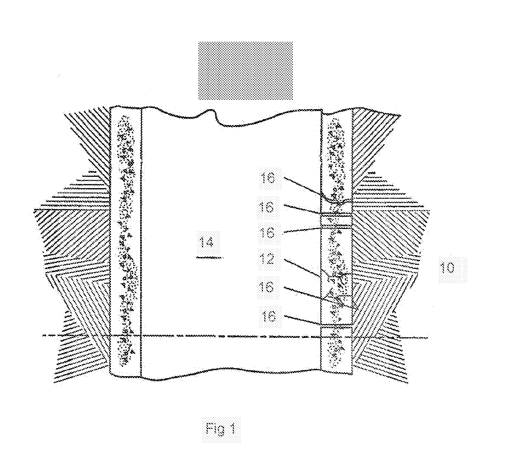
Generally, though it is not intended to be limiting, the passage may take the form of a cavity, fault, fissure, void or pore space through which fluid or gas may travel to cause leakage, flooding and / or contamination.

Method used


Image

  • Method of limiting permeability of a matrix to limit liquid and gas inflow
  • Method of limiting permeability of a matrix to limit liquid and gas inflow
  • Method of limiting permeability of a matrix to limit liquid and gas inflow

Examples


example 1

Potassium Permanganate and Ethanol as Curing Agent

[0091]In this example, an equal mass of potassium permanganate solution (40 g / L) and ethanol (combination acting as the curing agent) was combined with moderately saline water (synthesised to have characteristics of water present in many geological formations requiring treatment for prevention of water inflow). This combined liquid was added to 60% of a latex based grout composition (sold under the proprietary trade name NOH2O). Proportion of curing agent to grout component was modified to effect variation in rate of coagulation / setting of the sealing composition. The results are shown in Table 1.

TABLE 1Setting / coagulation of latex based grout composition with curingagent (potassium permanganate solution and ethanol)Wt % in curing agentKMnO4Time since mixing to achieveSaline watersolutionEtOHsolid mass962.02.0Some solid after 20 mins; mostly solidafter 16 hours924.04.0Some solid after 20 mins; mostly solidafter 16 hours928.0nonePartl...

example 2

Potassium Permanganate and Alcohol as Curing Agent with 60% Latex Based Grout Composition

[0093]A combination of potassium permanganate and alcohol was used to coagulate or set a 60% latex based grout component (sold under the proprietary name NOH2O). Rate of coagulation was altered by using a different alcohol to ethanol in combination with the permanganate solution. For example, it was postulated that adding an alcohol with more than one hydroxyl (OH) group instead of ethanol could alter the coagulation delay time or increase the rigidity of the grout once set. To test this, several different liquid polyols were combined with permanganate solution and then added to and mixed with 60% latex based grout component. The results of this testing are shown in Table 2. Best overall coagulation in the proportions tested was achieved using ethylene glycol in combination with permanganate solution.

TABLE 2Coagulation of 60% latex based grout component with potassiumpermanganate solution and va...

example 3

Potassium Permanganate as Curing Agent with 60% Latex Based Grout Component

[0094]A range of proportions of 40 g / L permanganate solution as curing agent, in proportions from 1 wt % to 8 wt % was added to 60% latex based grout component (sold under proprietary name NOH2O) and progress of setting / coagulation monitored for up to 10 days. The results, shown in Table 3, indicate that between 4 and 8 wt % of permanganate solution was needed to produce a soft solid on mixing with 60% grout component.

TABLE 3Coagulation of 60% latex based grout component with potassiumpermanganate solution as curing agentTime since60% groutCuring agentmixing toMasswt % inWt % KMnO4achieve solidDescription 10 days(g)mixsolutionmass (mins)after mixing24.7599.01.0N / ASlightly thick liquid24.5098.02.0N / AThick liquid24.0096.04.02.0Soft solid - paste23.0092.08.02.0Soft solid

[0095]Oxidation of organic hydroxyl groups by the permanganate ion KMnO4− is catalysed by the presence of either acid or base. The dispersion of...


PUM


Abstract

A method of limiting or reducing permeability of a matrix to liquid or gas flow is described. The method includes limiting inflow of water and / or gas into passages such as cavities, fissures, voids and the like, encountered in formations such as geological formations. The method includes steps of measuring one or more parameters relating to the matrix and selecting one or more components of a multi-component sealing composition with reference to the measured parameters. The selected components are introduced into the passage where it is set or coagulated to form a seal. Method is also described whereby the passage is sealed with a sealing composition comprising a grout component and a grout curing agent. A portion of the grout component is mixed with a portion of grout curing agent, the ratio of each being selected with reference to the measured parameters. The combined grout / curing agent are introduced into the passage where rate of curing or setting is controlled by modifying the ratio.

Description

FIELD OF THE INVENTION[0001]The present invention relates to a method of limiting or reducing permeability of a matrix to liquid or gas inflow, including limiting inflow into passages such as cavities, fissures, voids, open features and pore spaces encountered in formations such as geological formations.BACKGROUND TO THE INVENTION[0002]Methods of attempting to substantially seal or otherwise reduce the permeability of a matrix such as concrete, rock or soil are known. For example, regular cement based suspension grouts can be introduced into voids, opens spaces and pore spaces around a mine shaft in order to attempt to seal fissures or reduce the permeability of unconsolidated sand or soil around the shaft, thereby limiting liquid inflow into the shaft.[0003]Typically, a volume of grout or sealing composition product is transported to the site to be treated and applied to the passage or passages requiring sealing to prevent water inflow. Application typically involves pumping of gro...

Claims


Application Information

Patent Timeline
Patent Type & Authority Applications(United States)
IPC IPC(8): E02D3/12E02D37/00E02D31/10
CPCE02D3/12E02D37/00E02D31/10C09K8/44C09K8/50C09K8/508E02D31/14E21B33/138
Inventor VAN DYK, DEONGROBLER, NICO JOHAN
Owner RELBORGN
Learn More