Light emitting element
a technology of light-emitting elements and electrodes, which is applied in the direction of basic electric elements, electrical equipment, semiconductor devices, etc., can solve the problems of insufficient emission to achieve uniformity, and achieve the effect of reducing the uneven distribution of current density between electrodes
- Summary
- Abstract
- Description
- Claims
- Application Information
AI Technical Summary
Benefits of technology
Problems solved by technology
Method used
Image
Examples
example 1
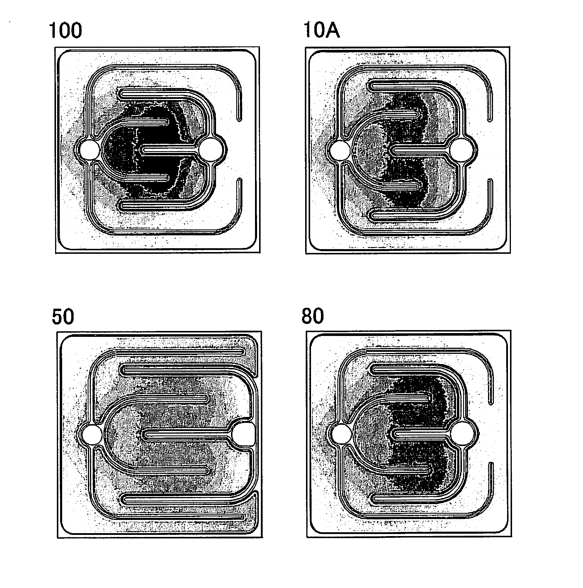
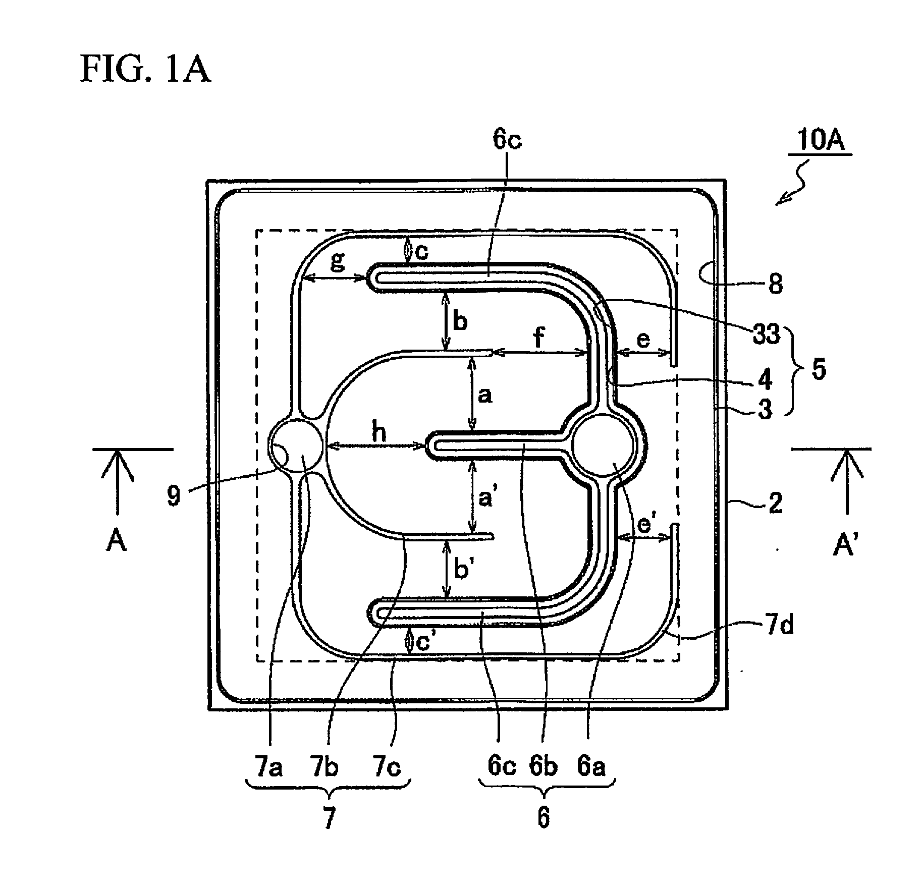
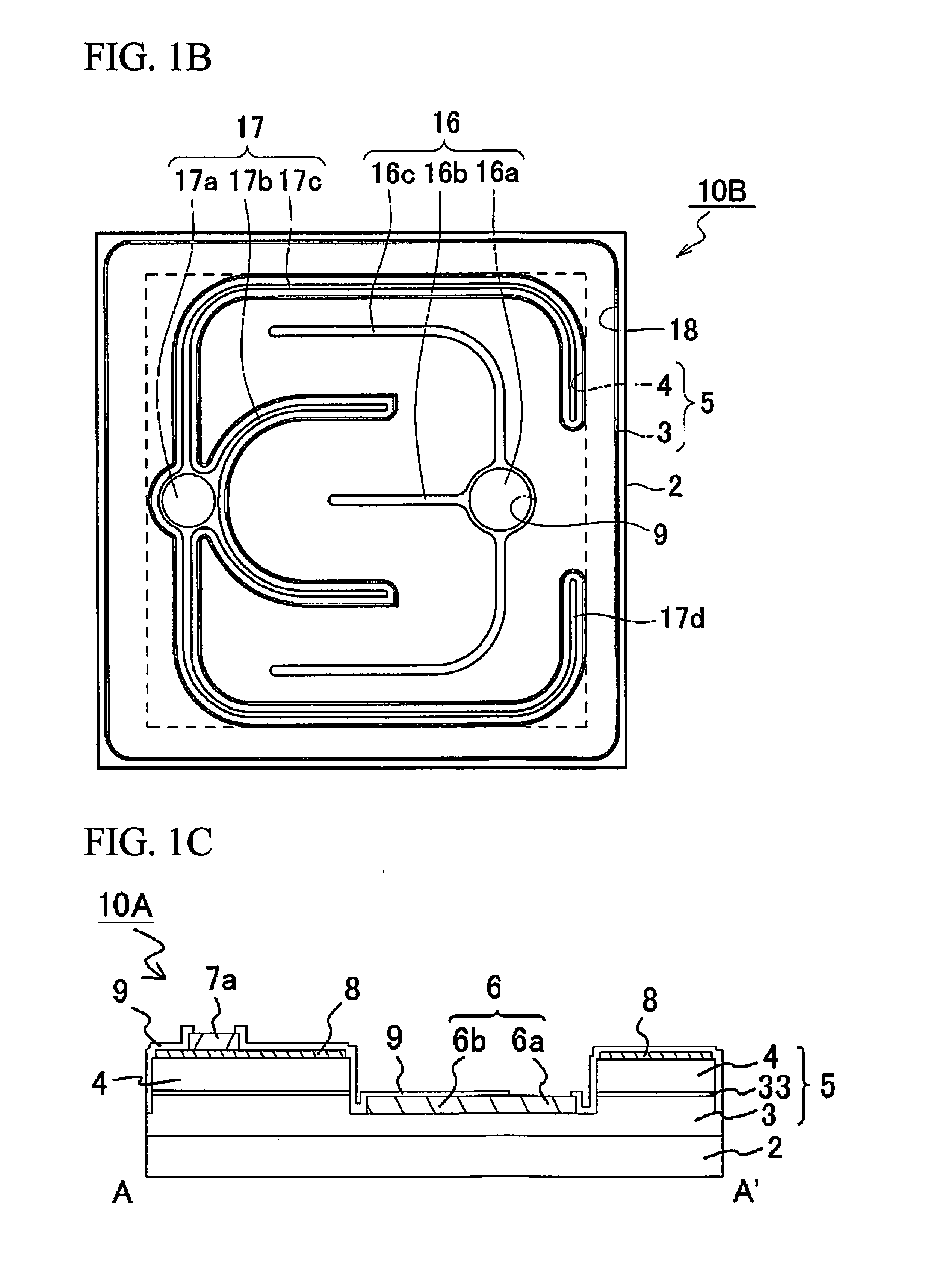
[0088]As shown in FIGS. 1A and 1C, the light emitting element 10A in Example 1 has a substrate 2, a semiconductor stack 5 having an n-type semiconductor layer 3 (a first conductivity type semiconductor layer), an active layer 33, and a p-type semiconductor layer 4 (a second conductivity type semiconductor layer) provided in that order over the substrate 2, an n-side electrode (a first electrode 6) formed on the n-type semiconductor layer 3, and a p-side electrode (a second electrode 7) that is disposed on the p-type semiconductor layer 4 and surrounding the n-side electrode.
[0089]The substrate 2 and the semiconductor stack 5 (in particular, the p-type semiconductor layer 4) has an approximately square shape in a plan view, the length of a side of the semiconductor stack 5 or the substrate 2 is 800 μm.
[0090]The first electrode 6 (the n-side electrode) is formed on the n-type semiconductor layer 3 at the part of the semiconductor stack 5 exposed by removing part of the p-type semicond...
modification example 1 of example 1
[0109]As shown in FIG. 1B, the light emitting element 10B of this Modification Example 1 of Example 1 has substantially the same configuration as the light emitting element 10A in Example 1, except that the first electrode 16 is the p-side electrode, and the second electrode 17 is the n-side electrode.
[0110]That is, the light emitting element 10B has a first electrode 16 as the p-side electrode, which has a first connecting portion 16a, a first extending portion 16b, and two second extending portions 16c. The the light emitting element 10B has a second electrode 17 as the n-side electrode, which has a second connecting portion 17a, two third extending portions 17b, and two fourth extending portions 17c. The distal ends 17d of these fourth extending portions 17c are bent toward the first connecting portion 16a.
[0111]The width of the first extending portion 16b is 12 μm.
[0112]The width of the second extending portion 16c is 12 μm.
[0113]The width of the third extending portion 17b is ...
modification example 2 of example 1
[0115]As shown in FIG. 1D, the light emitting element 10C of this Modification Example 2 of Example 1 is similar to the light emitting element 10A in that the second connecting portion 7a, the third extending portions 7b, and the fourth extending portions 7c are disposed at the second electrode 7, and has substantially the same configuration as the light emitting element 1 OA in Example 1 except that the distal ends of the fourth extending portions 7c are not bent, and extend linearly toward the end of the light emitting element 10C, past the outermost end of the first connecting portion 6a.
[0116]The distance between the distal ends of the fourth extending portions 7c near the end of the light emitting element and the end of the semiconductor stack 5 in the direction in which the fourth extending portions 7c extend parallel to the first extending portion 6b is 62 μm.
PUM
 Abstract
Description
Claims
Application Information
 - R&D
- Intellectual Property
- Life Sciences
- Materials
- Tech Scout
- Unparalleled Data Quality
- Higher Quality Content
- 60% Fewer Hallucinations
Browse by: Latest US Patents, China's latest patents, Technical Efficacy Thesaurus, Application Domain, Technology Topic, Popular Technical Reports.
© 2025 PatSnap. All rights reserved.Legal|Privacy policy|Modern Slavery Act Transparency Statement|Sitemap|About US| Contact US: help@patsnap.com


