
Alignment guide feature for metal to metal seal protection on mechanical connections and couplings

a technology of mechanical connection and guide feature, which is applied in the direction of hose connection, screw threaded joint, coupling, etc., can solve the problems of unable to assemble tubular members to one another without causing damage to the sealing surface, and unable to achieve the effect of fluid-tight sealing

Active Publication Date: 2015-05-28
VETCO GRAY
View PDF7 Cites 22 Cited by
  • Summary
  • Abstract
  • Description
  • Claims
  • Application Information

AI Technical Summary

Benefits of technology

This patent describes a way to protect the sealing surfaces of two tubular members that need to be connected. These protective features can be built into the design of the tubular members and can help keep them aligned properly. This alignment can make it easier to create a tight seal between the tubular members.

Problems solved by technology

One challenge of working with integral metal-to-metal seals is preventing damage to the surface finish on the sealing surfaces, and thereby facilitating effective formation of fluid-tight connections.
Tubular members, and the oilfield equipment used to transport and handle the tubular members, are often large and cumbersome.
Thus, assembling tubular members to one another without causing damage to the sealing surfaces can be difficult.
For example, due to the large masses of the tubular members and oilfield equipment, even low-speed collisions can produce sufficient force to damage the sealing surfaces while attempting to land or align a tubular member.
These protectors add cost and, depending on the protector design, can be dislodged from a tubular member and lost.
The removal of these protectors can slow the assembly process and leave the sealing surfaces exposed during a stage of assembly where the sealing surfaces are at risk.

Method used


Image

  • Alignment guide feature for metal to metal seal protection on mechanical connections and couplings
  • Alignment guide feature for metal to metal seal protection on mechanical connections and couplings
  • Alignment guide feature for metal to metal seal protection on mechanical connections and couplings

Examples


Embodiment Construction

[0016]The present invention will now be described more fully hereinafter with reference to the accompanying drawings which illustrate embodiments of the invention. This invention may, however, be embodied in many different forms and should not be construed as limited to the illustrated embodiments set forth herein. Rather, these embodiments are provided an that this disclosure will be thorough and complete, and will fully convey the scope of the invention to those skilled in the art. Like numbers refer to like elements throughout, and the prime notation, if used, indicates similar elements in alternative embodiments.

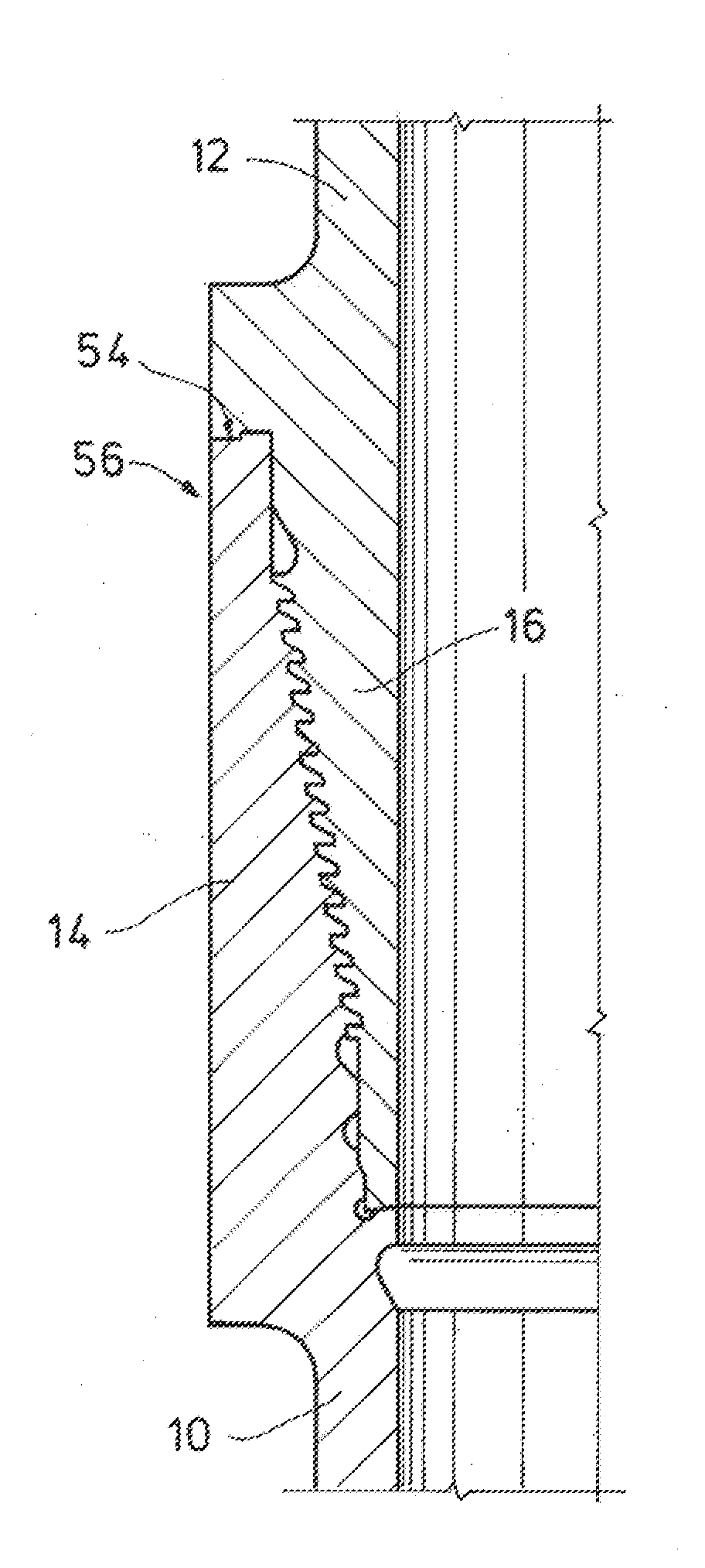
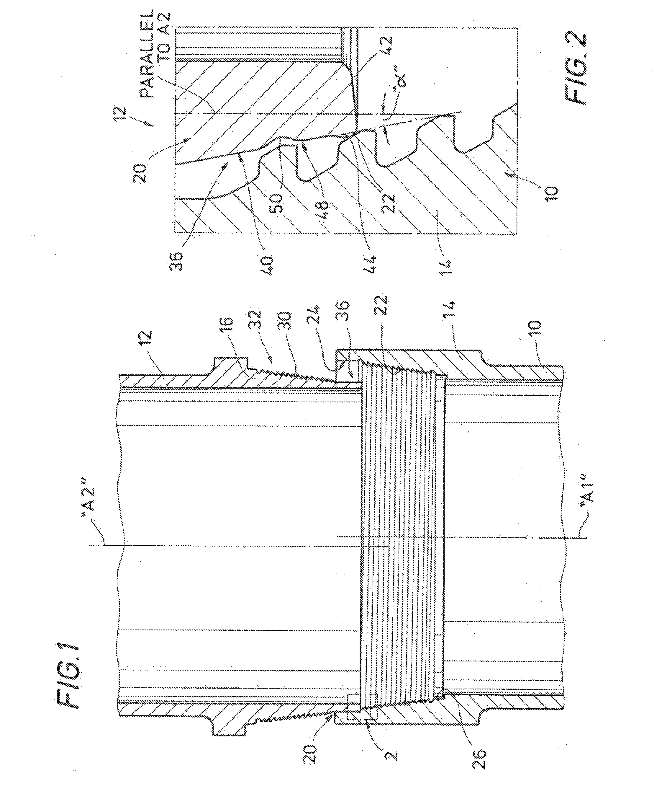
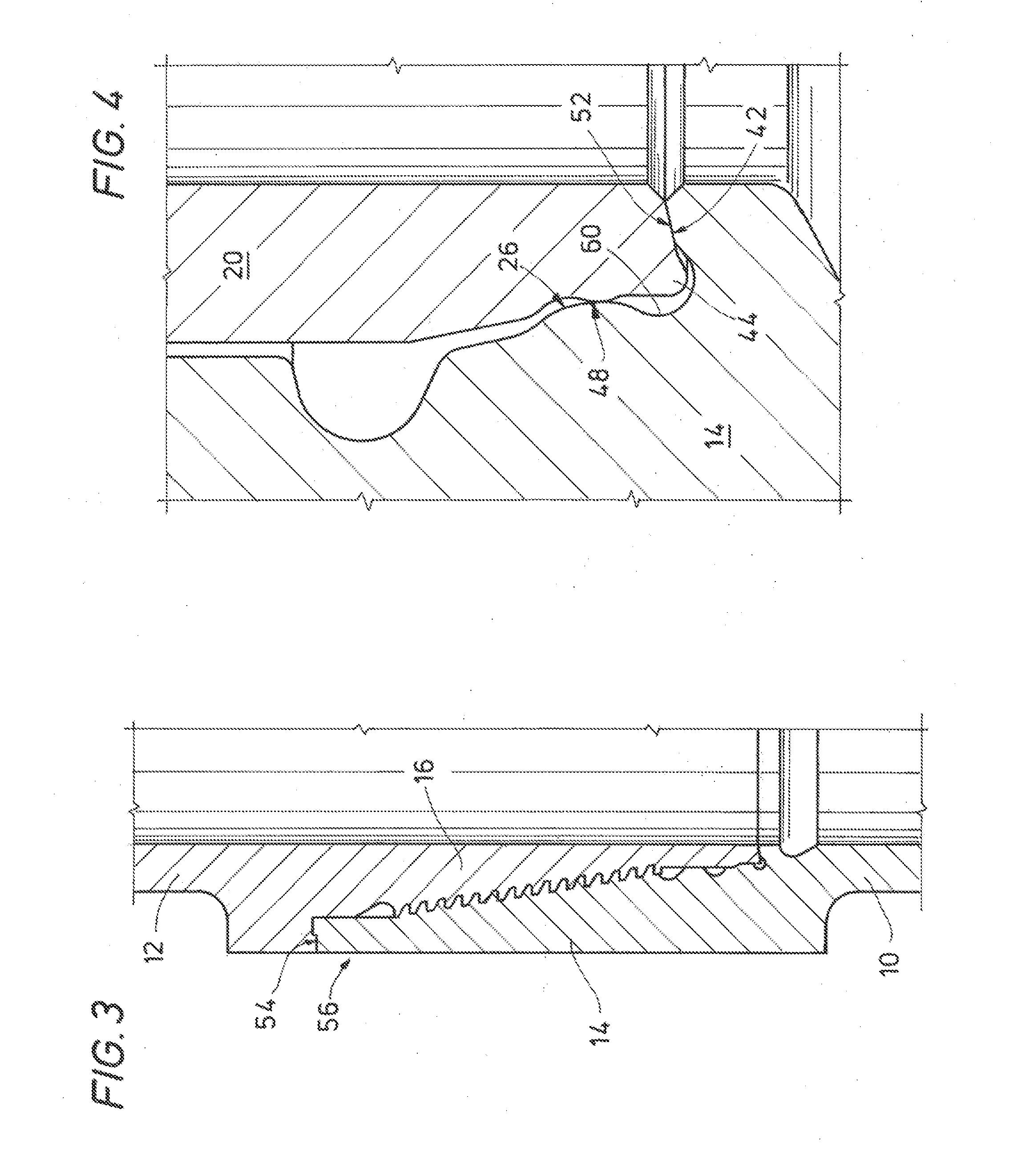
[0017]Referring to FIG. 1, a first tubular member 10 and a second tubular member 12 comprise sections of casing for completing a wellbore (not shown). In other embodiments, first and second tubular members 10, 12 comprise other wellbore components such as wellhead housing components, tubing string sections, pipe, riser sections, drill string sections, etc. The first tubu...


PUM


Abstract

A connection is established between a pin connector and a box connector defined on a pair of tubular members such as casing segments in the field of oil and gas recovery. The pin connector and box connector include features for the protection of metallic-sealing surfaces during assembly, disassembly, transport and handling of the tubular members. The pin connector includes a stabbing flank with an inwardly tapered annular flank surface thereon, and an alignment protrusion extending outward with respect to the pin-side metallic sealing surface in a direction normal to a cone angle defined by the inwardly tapered annular flank surface. The alignment protrusion engages internal surfaces of the box connector to concentrically align the pin connector with the box connector, and thereby protects the metallic sealing surfaces from damage that might otherwise result from collisions between the pin connector and the box connector.

Description

RELATED APPLICATION[0001]This application claims the benefit of and priority to U.S. Provisional Patent Application No. 61 / 907,687, titled “Alignment Guide Feature for Metal to Metal Seal Protection on Mechanical Connections and Couplings” filed Nov. 22, 2013, which is incorporated herein by reference in its entirety.BACKGROUND OF THE INVENTION[0002]1. Field of the Invention[0003]The present invention relates in general to connecting tubular members, e.g., in the field of oil and as recovery. In particular, the disclosure relates to the alignment and connection of adjacent tubular members within a wellbore, e.g., the installation of a casing segment into a wellbore to form a fluid seal with an adjacent casing segment.[0004]2. Brief Description of Related Art[0005]A variety of wellbore operations include the connection of adjacent tubular members such as pipe, drill string, riser sections, casing segments, and the like. Some of the joints established between the tubular members can e...

Claims


Application Information

Patent Timeline
IPC IPC(8): E21B17/042F16L15/00
CPCF16L15/002E21B17/042F16L15/001F16L37/24F16L15/004
Inventor ZHU, BAOZHIPALLINI, JOSEPH W.STEEN, THOMASPATTERSON, JR., WILLIAM R.
Owner VETCO GRAY
Learn More