
Image processing device and image processing method

a processing device and image technology, applied in image enhancement, image analysis, instruments, etc., can solve the problems of not being able to maintain a texture, not being able to eliminate only noise, and affecting the detail of an image, so as to achieve stronger smoothing strength

Inactive Publication Date: 2015-05-21
RICOH KK
View PDF3 Cites 12 Cited by
  • Summary
  • Abstract
  • Description
  • Claims
  • Application Information

AI Technical Summary

Benefits of technology

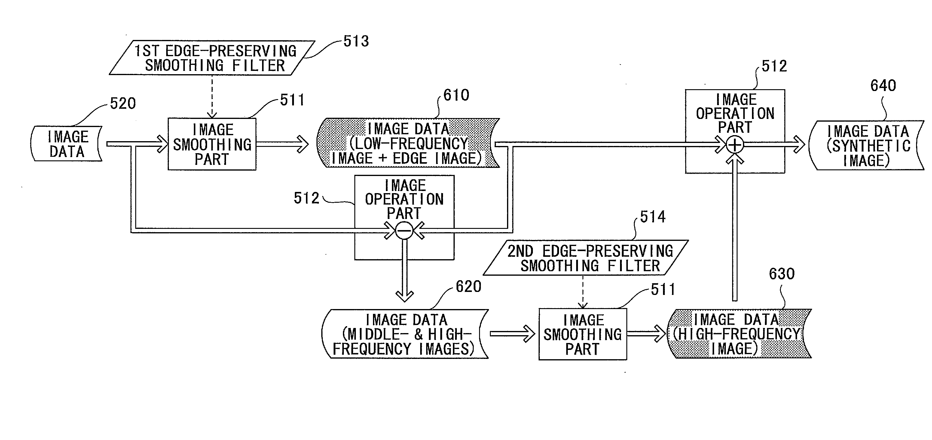
[0009]According to one aspect of the present invention, there is provided an image processing device, including a first production part configured to apply a first smoothing process to an original image data by using a first edge-preserving smoothing filter to produce first image data that include a low-frequency image and an edge image, a second production part configured to apply a second smoothing process to a differential image between the original image data and the first image data to produce second image data that include a high-frequency image, and a synthesis part configured to synthesize the first image data and the second image data.
[0010]According to another aspect of the present invention, there is provided an image processing device, including a first production part configured to apply a first smoothing process to an original image data by using a first edge-preserving smoothing filter to produce intermediate image data that include a low-frequency image, a middle-frequency image, and an edge image, and apply a second smoothing process to the intermediate image data by

Problems solved by technology

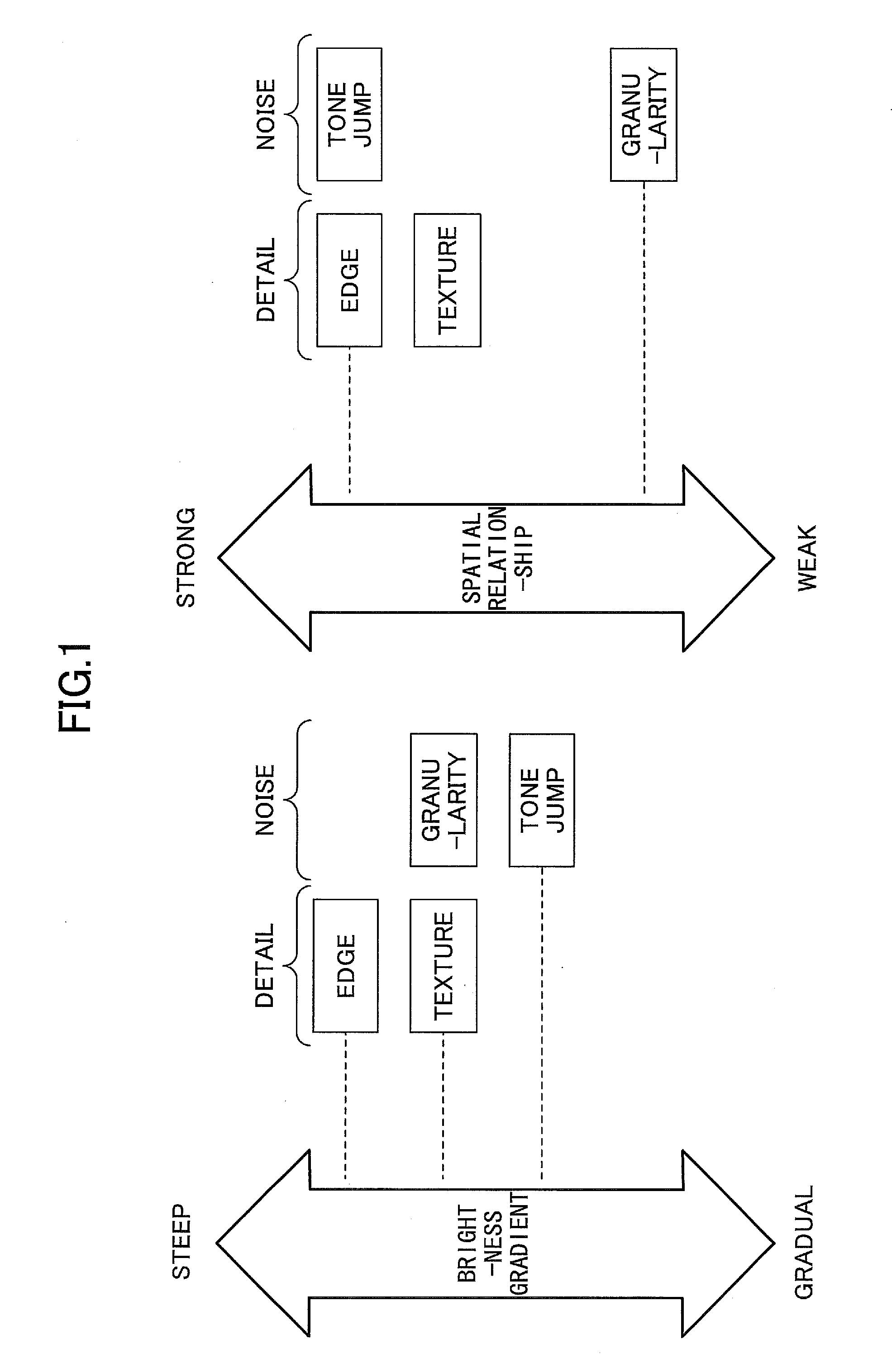
However, in a case where a smoothing filter or the like is used, there is a problem that a detail of an image, such as a texture or an edge, is impaired, although it is possible to suppress a “noise” on an image such as a granularity or a tone jump.
However, in a case of an image processing technique disclosed in Japanese Patent No. 3939428, it is not possible to maintain a texture although an edge as a detail is maintained.
This is because it is not possible to extract a high-frequency image such as a texture from original image data by merely executing an edge-preserving smoothing process and calculating a differential value between before and after the process so that it is not possible to eliminate only a noise.

Method used


Image

  • Image processing device and image processing method
  • Image processing device and image processing method
  • Image processing device and image processing method

Examples


second embodiment

A Second Embodiment

[0099]In the first embodiment described above, a configuration is provided in such a manner that a smoothing process is executed for the image data 620 that include a middle-frequency image and a high-frequency image by using an edge-preserving smoothing filter so as to produce image data that include a high-frequency image.

[0100]However, an embodiment of the present invention is not limited thereto. For example, a smoothing process may be executed for the image data 620 that include a middle-frequency image and a high-frequency image by using a smoothing filter so as to produce image data that include a middle-frequency image. Then, a configuration may be provided in such a manner that a differential value between image data that include a middle-frequency image and a high-frequency image and image data that include a middle-frequency image is calculated to produce image data that include a high-frequency image. The present embodiment will be described in detail ...

third embodiment

A Third Embodiment

[0123]The first embodiment described above is configured in such a manner that one edge-preserving smoothing filter is utilized to produce the image data 610 that include a low-frequency image and an edge image and further one edge-preserving smoothing filter is utilized to produce the image data 630 that include a high-frequency image. However, an embodiment of the present invention is not limited thereto. For example, a configuration may be provided in such a manner that one edge-preserving smoothing filter is utilized to produce the image data 630 that include a high-frequency image and further one edge-preserving smoothing filter is utilized to produce the image data 610 that include a low-frequency image and an edge image. The present embodiment will be described in detail below.

[0124]First, a functional configuration of an image processing part 510 of an image processing device 500 according to the present embodiment will be described. FIG. 10 is a block dia...

fourth embodiment

A Fourth Embodiment

[0144]A configuration in the first to third embodiments described above is provided in such a manner that image data that include a low-frequency image and an edge image and image data that include a high-frequency image are synthesized to produce a synthetic image but an embodiment of the present invention is not limited thereto.

[0145]For example, a configuration may be provided in such a manner that an image correction process is executed for each of image data that include a low-frequency image and an edge image and image data that include a high-frequency image and both of them are synthesized. Even when an image correction process is executed for these image data, a noise is not enhanced, because such a noise (a granularity and / or a tone jump) has been eliminated. The present embodiment will be described in detail below.

[0146]First, a configuration of an image processing device according to the present embodiment will be described. FIG. 12 is a diagram that ...


PUM


Abstract

An image processing device includes a first production part configured to apply a first smoothing process to an original image data by using a first edge-preserving smoothing filter to produce first image data that include a low-frequency image and an edge image, a second production part configured to apply a second smoothing process to a differential image between the original image data and the first image data to produce second image data that include a high-frequency image, and a synthesis part configured to synthesize the first image data and the second image data.

Description

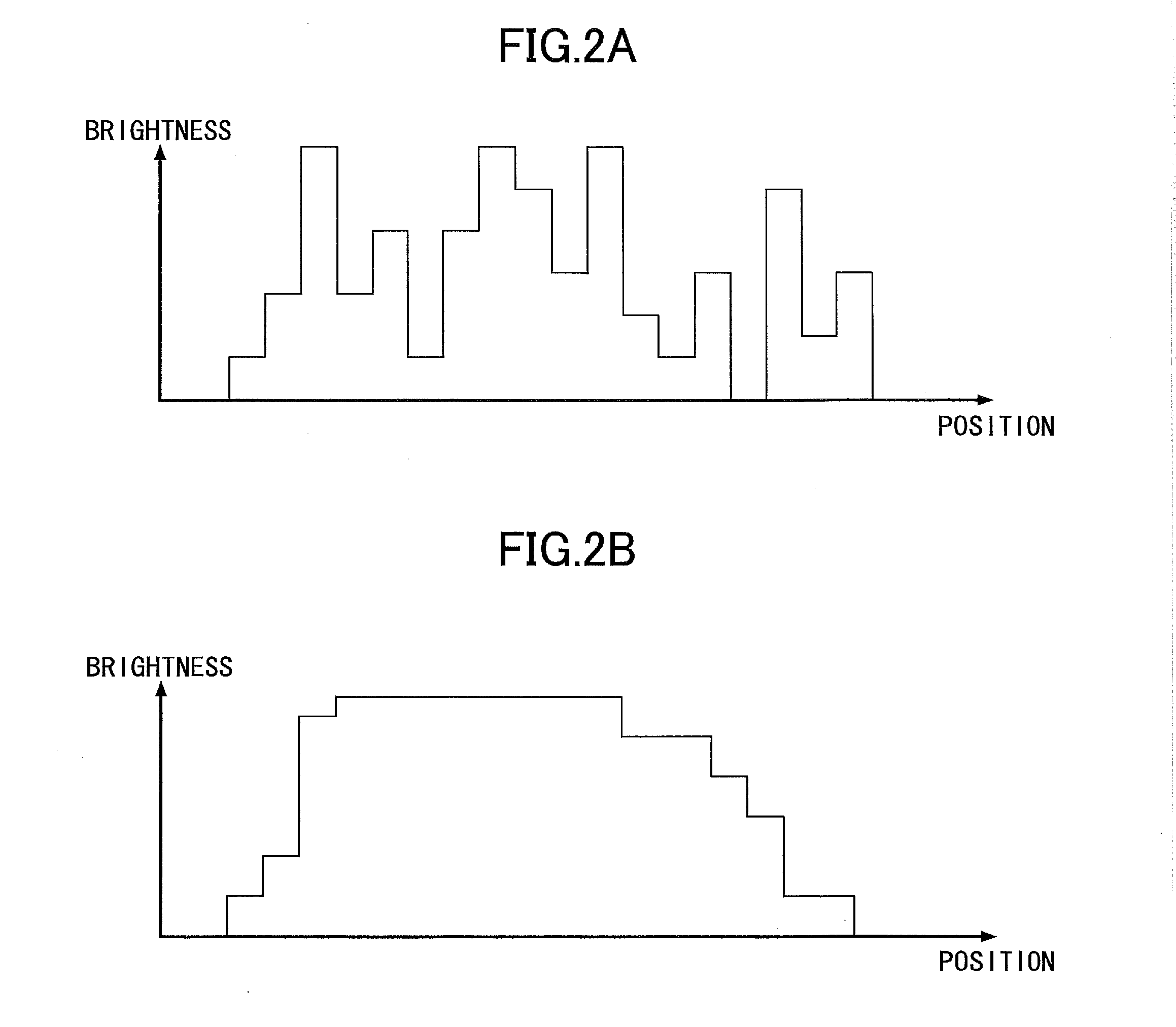
BACKGROUND OF THE INVENTION[0001]1. Field of the Invention[0002]An aspect of the present invention relates to at least one of an image processing device and an image processing method.[0003]2. Description of the Related Art[0004]As a typical noise that degrades image quality, a granularity or a tone jump is known. A granularity refers to a pattern like a fine dot to be found in a flat area of an image and a tone jump refers to a state that a tone discretely changes in an image.[0005]Because such a noise is caused more explicitly in a case where image processing such as a tone transformation is executed, it is desirable to preliminarily reduce the noise by using a smoothing filter or the like.[0006]However, in a case where a smoothing filter or the like is used, there is a problem that a detail of an image, such as a texture or an edge, is impaired, although it is possible to suppress a “noise” on an image such as a granularity or a tone jump. Accordingly, an image processing techniq...

Claims


Application Information

Patent Timeline
IPC IPC(8): G06T5/00G06T5/50G06T5/20
CPCG06T5/002G06T5/20G06T2207/20216G06T2207/20024G06T2207/20182G06T5/50G06T2207/20192G06T5/70
Inventor NAKAMURA, SATOSHI
Owner RICOH KK
Learn More