
Seismic survey shot coordination apparatus method and system

a shot coordination and seismic survey technology, applied in the field of seismic survey shot coordination apparatus method and system, can solve the problems of difficult radio communication, time-consuming, error-prone process,

Inactive Publication Date: 2015-05-21
CGG SERVICES SA
View PDF5 Cites 6 Cited by
  • Summary
  • Abstract
  • Description
  • Claims
  • Application Information

AI Technical Summary

Benefits of technology

The patent text describes methods and systems for controlling impulsive sources during a geophysical survey. The technical effects of this patent include improved accuracy and efficiency in controlling the detonation of impulsive sources in a safe manner. The methods and systems also prevent unauthorized detonations and reduce the risk of injury or damage to equipment.

Problems solved by technology

In some environments, radio communications may be difficult and miscommunications may occur.
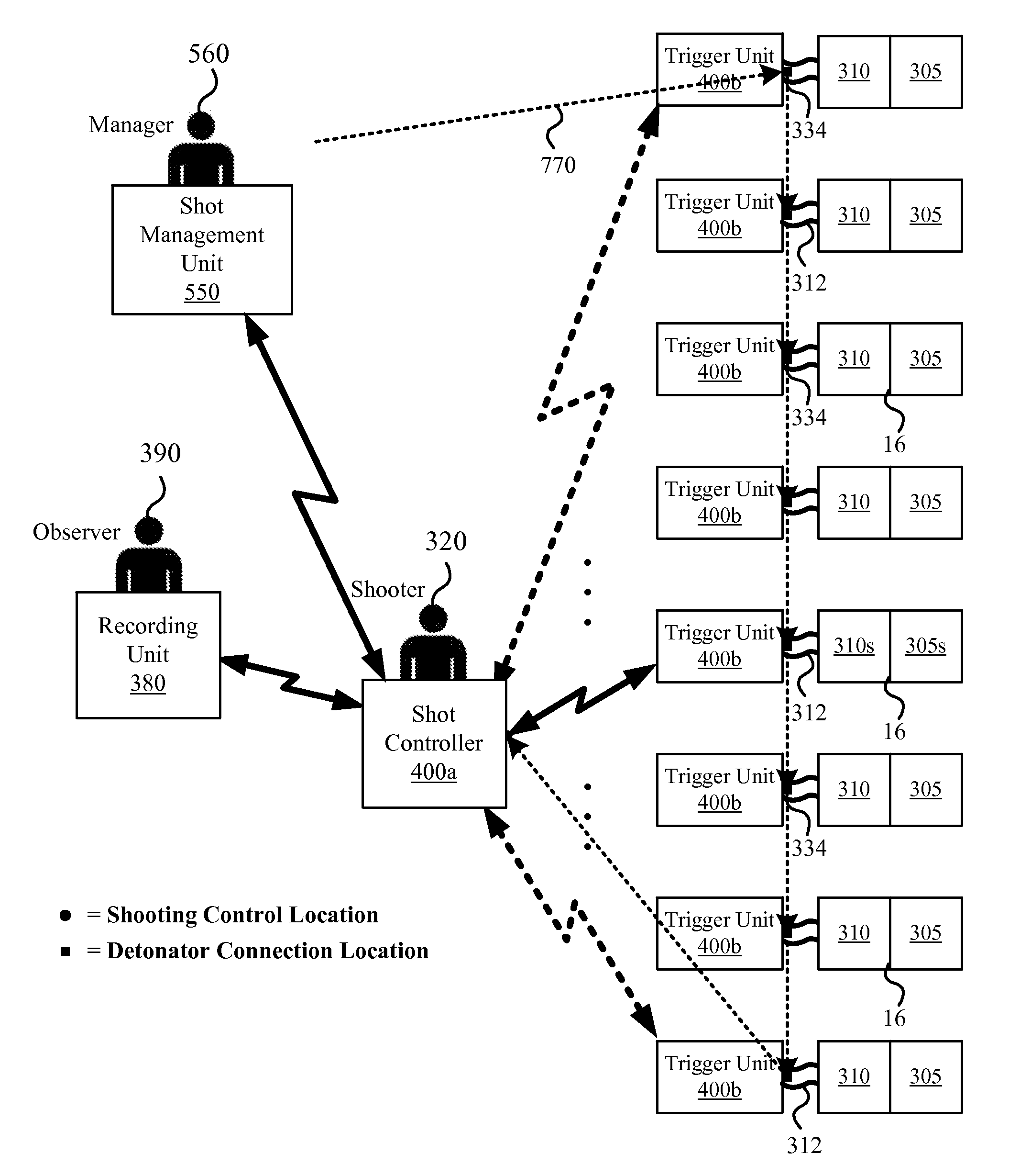
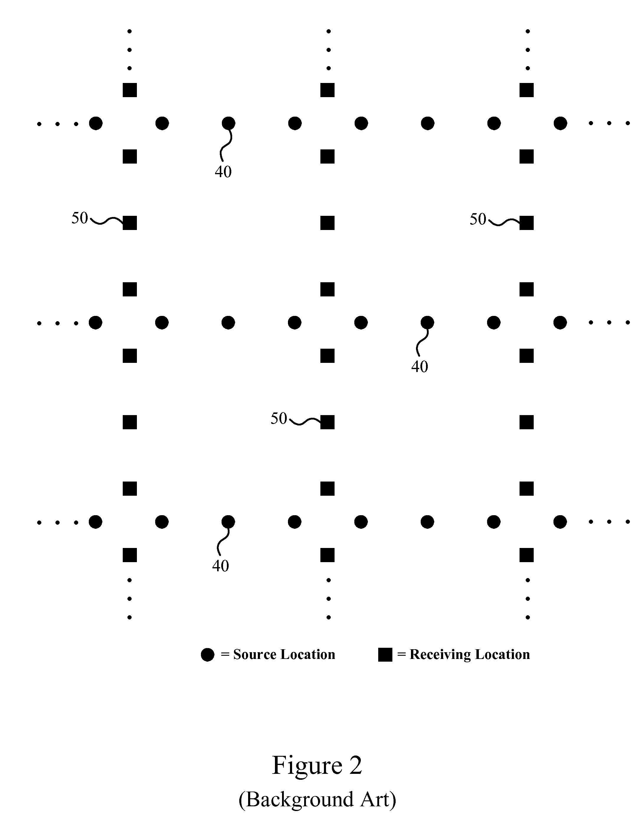
The reader may appreciate that coordinating the movement of the shooters 320 and the firing of the sources 16 at a large number of source locations 40 may be a tedious, time consuming, and error prone process.
In the case of sources 16 with explosive charges 305, it is a process that is also potentially very dangerous.
The delays and costs associated with such activities are typically prohibitive.
Furthermore, as the density of shot locations (which are currently as little as 5 meters apart) continues to increase in order to provide higher resolution seismic data, field crews are experiencing a number of issues with the shot coordination system 300.
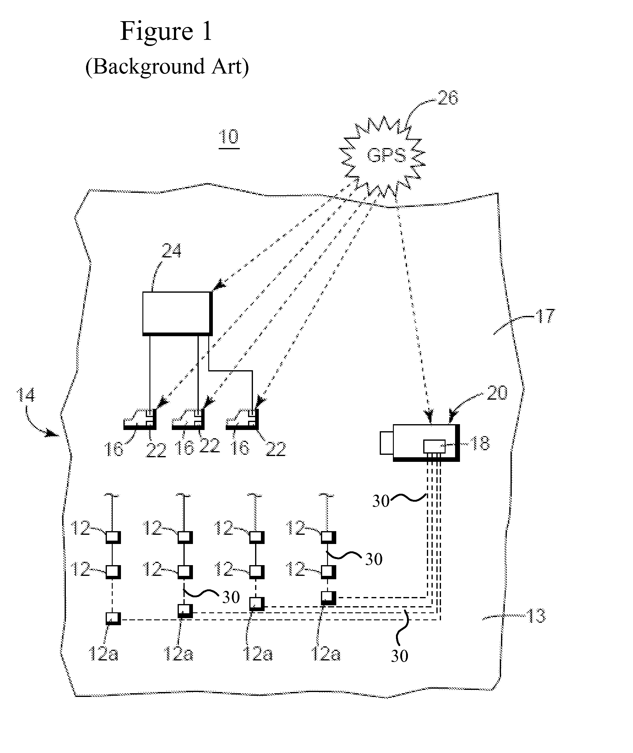
In addition to issues with advancing and retreating, determining the actual location of the impulsive source at the time of shooting is problematic in that the shooter (and therefore the positioning device of the shot controller 330) must typically be positioned at least 30 meters away from the source 16 for safety reasons.

Method used


Image

  • Seismic survey shot coordination apparatus method and system
  • Seismic survey shot coordination apparatus method and system
  • Seismic survey shot coordination apparatus method and system

Examples


Embodiment Construction

[0031]The following description of the exemplary embodiments refers to the accompanying drawings. The same reference numbers in different drawings identify the same or similar elements. The following detailed description does not limit the invention. Instead, the scope of the invention is defined by the appended claims.

[0032]Reference throughout the specification to “one embodiment” or “an embodiment” means that a particular feature, structure, or characteristic described in connection with an embodiment is included in at least one embodiment of the subject matter disclosed. Thus, the appearance of the phrases “in one embodiment” or “in an embodiment” in various places throughout the specification is not necessarily referring to the same embodiment. Further, the particular features, structures, or characteristics may be combined in any suitable manner in one or more embodiments.

[0033]U.S. Pat. No. 8,451,686, which is incorporated herein by reference, describes a method for coordinat...


PUM


Abstract

A system for controlling impulsive sources during a geophysical survey includes a triggering unit that interfaces to an impulsive source and provides an estimated current location for the impulsive source and a shot controller configured to transmit a detonation authorization to the triggering unit. The shot controller or the triggering unit may inhibit detonation of an impulsive source connected to the selected triggering unit if an estimated current location of the impulsive source is substantially different than an intended shot location. A corresponding apparatus and method are also disclosed herein.

Description

BACKGROUND[0001]1. Technical Field[0002]Embodiments of the subject matter disclosed herein generally relate to the field of geophysical data acquisition and processing. In particular, the embodiments disclosed herein relate to apparatuses, methods, and systems for coordinating impulsive sources during a geophysical survey such as a seismic survey.[0003]2. Discussion of the Background[0004]Geophysical data is useful for a variety of applications such as weather and climate forecasting, environmental monitoring, agriculture, mining, and seismology. As the economic benefits of such data have been proven, and additional applications for geophysical data have been discovered and developed, the demand for localized, high-resolution, and cost-effective geophysical data has greatly increased. This trend is expected to continue.[0005]For example, seismic data acquisition and processing may be used to generate a profile (image) of the geophysical structure under the ground (either on land or ...

Claims


Application Information

Patent Timeline
IPC IPC(8): G01V1/104
CPCG01V1/104
Inventor JUROK, JASONPREUSSER, TOM
Owner CGG SERVICES SA
Learn More