Sealed LED Light Module

a led light module and led light technology, applied in semiconductor devices for light sources, lighting and heating apparatus, lighting support devices, etc., can solve the problems of high design cost and respective complexity, and achieve the effect of increasing the mechanical stability of the mechanical conta

Inactive Publication Date: 2015-05-21
LUNUX GMBH
View PDF4 Cites 1 Cited by
  • Summary
  • Abstract
  • Description
  • Claims
  • Application Information

AI Technical Summary

Benefits of technology

[0009]The problem to be solved by the invention is to design a sealed LED light module which is sealed against dust, dirt, water and / or humidity, which has excellent long term stability and which can be manufactured by an automated process in large volumes at low costs.
[0013]Preferably, the base plate and the cover form a hermetically sealed unit which preferably is water tight and which preferably cannot be opened and need not to be opened for service. This prevents the penetration of dust and debris into the optical system which also extends lifetime and improves quality. Most preferably the base plate has no further holes or openings except holes which are sealed and ventilation holes. Due to the elastic properties of the seal, different thermal expansion of the base plate and the cover may be equalized, therefore preventing cracks or even bending of the unit at extreme temperatures.
[0015]In a further preferred embodiment, there is at least one sealing sidewall located between the cover and the base plate for sealing the inner space between the cover and the base plate containing the at least one LED against the outer environment. The sealing sidewall may enclose an area within which a further hole or opening may be provided in the base plate and / or the cover. Such an opening may be used for contacting an electrical connector and / or for inserting a screw. The sealing sidewall may be extending from the cover and may be of the same material as the cover. In an alternative embodiment, the sidewall may be of a material which is the same as the sealing. There may be any combination of the sealings disclosed herein with a connector. Generally such a sealed opening prevents any debris or contamination from the connector to penetrate into the optical system.
[0016]In a further embodiment, there may be an upper sealing which further seals parts of the outer side of the base plate. This upper sealing preferably is of the same material as the first sealing. To simplify molding, it may be connected by at least one bar to the first sealing. The upper sealing may also extend from the outside of the base plate through the inner space between the base plate and the cover to the inner side of the cover, therefore also sealing the inner space against the environment.
[0018]In another embodiment, the edges of the base plate are bent to further in-crease mechanical strength of the connection to the sealing and to increase the mechanical stability of the mechanical contact between the base plate and the sealing.

Problems solved by technology

A disadvantage of these LED light units is their respective complex and thus expensive design.

Method used


Image

  • Sealed LED Light Module
  • Sealed LED Light Module
  • Sealed LED Light Module

Examples


Embodiment Construction

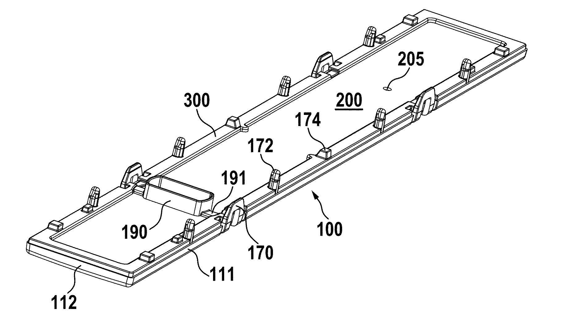
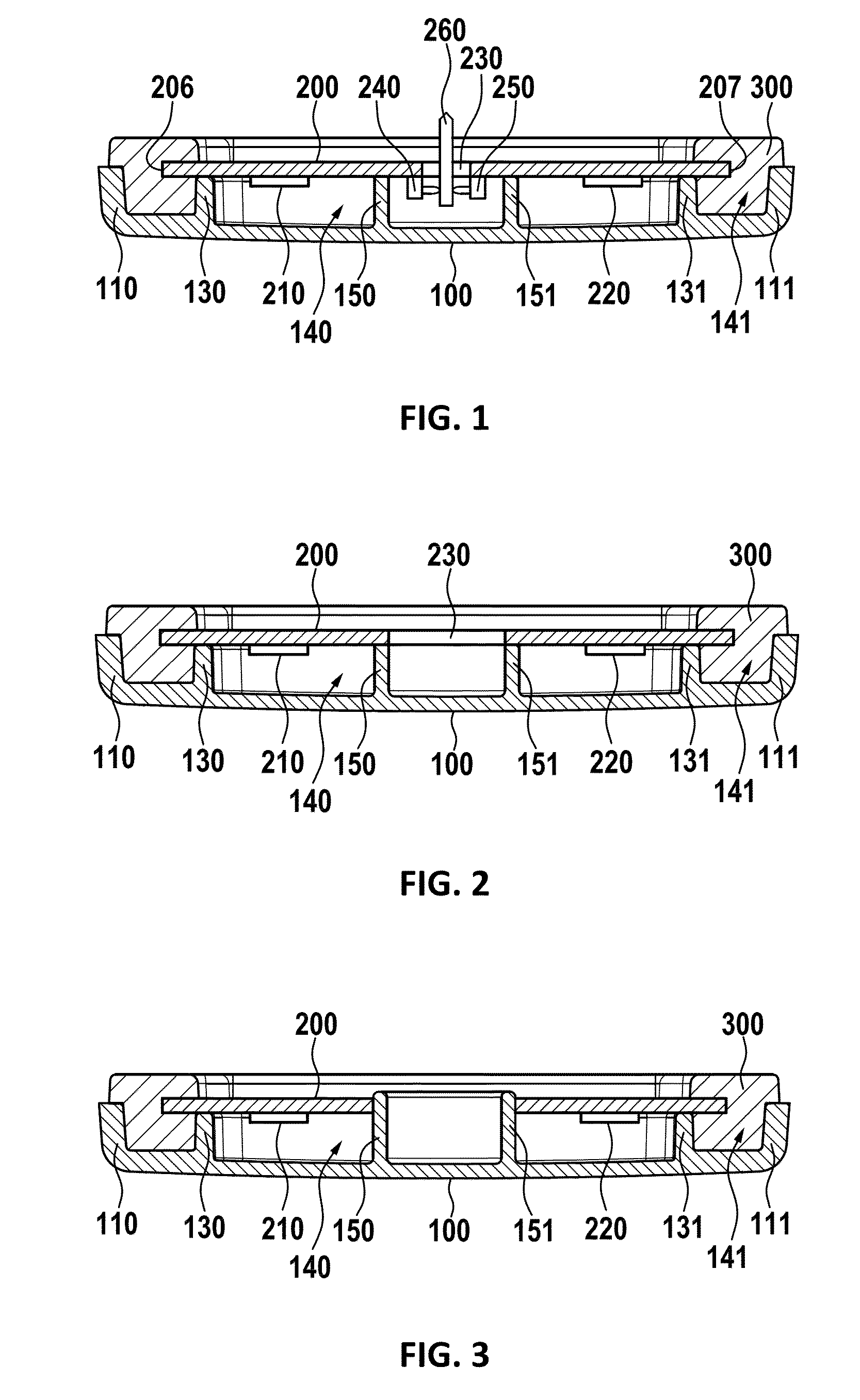
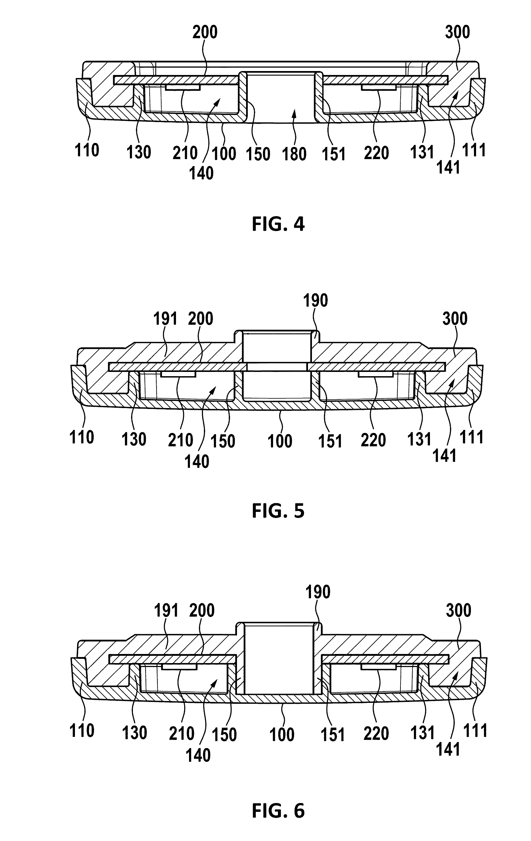
[0031]In FIG. 1, a sectional view of a first embodiment of the invention is shown. A cover 100 holds a base plate 200, whereas fixing and sealing between the cover and the base plate is done by a sealing 300. The base plate has an outer side (on top in the figure) and an inner side directed towards the cover, the inner side holds at least one LED (Light Emitting

[0032]Diode) 210, 220, and optionally further electronic components. The LEDs radiate light from the bottom side through the cover 100 to the outside of the light module. For better holding of the base plate, preferably at least one base plate support 130, 131 are provided within the cover. They are preferably protruding from the surface of the cover. Furthermore, it is preferred, if the cover has at least one sidewall 110, 111, which preferably forms at least one trench 141 which may be filled with sealing 300 which preferably seals the edges 206, 207 of the base plate 200. Between the base plate 200 and the cover 100, there...


PUM


Abstract

A sealed LED light module comprises a base plate, having at least one LED, and a cover providing a base plate support. The base plate is located on the cover to define an inner space which is sealed against the environment. For sealing the cover has at least one sidewall, which defines a trench together with at least one base plate support, and the trench holds a seal which interacts with at least one edge of the base plate and the surface of the trench to seal the inner space against the environment.

Description

PRIORITY CLAIM[0001]This application is a continuation of pending International Application No. PCT / EP2013 / 065806 filed on Jul. 26, 2013, which designates the United States and claims priority from European Application No. 12178841.8 filed on Aug. 1, 2012, both of which are incorporated herein by reference in their entireties.BACKGROUND OF THE INVENTION[0002]1. Field of the Invention[0003]The invention relates to a LED (Light Emitting Diode) light unit and specifically to a housing for a LED light unit.[0004]2. Description of Relevant Art[0005]In LED light units, a plurality of LEDs may be mounted to a printed circuit board. This circuit board is often covered by a cover which may also act as a lens for guiding light to the outside of the light unit.[0006]The European patent application publication EP 1 821 030 A1 discloses a LED light unit, where LEDs are mounted to a heat sink. Furthermore, the LEDs are embedded by a cover element and a housing to form an integral part which is wa...

Claims


Application Information

Patent Timeline
Patent Type & Authority Applications(United States)
IPC IPC(8): F21V31/00F21V23/06
CPCF21V31/005F21Y2101/02F21V23/06F21K9/20F21V3/00F21V15/01F21V19/005F21V23/002F21Y2115/10F21V23/009
Inventor JELINEK, MARKBRUMMEL, REINHOLDFELDKAMP, HORSTKERPE, ALEXANDER
Owner LUNUX GMBH
Why Eureka
Try Eureka