
Structure Modelling and Maintenance Scheduling

a technology of structure and maintenance schedule, applied in the field of computer assisted modeling of structures, can solve the problems of high cost of a deficient maintenance program, early replacement of the structure or of expensive components of the structure, and the ongoing and resource intensive activity of maintenance of the structur

Inactive Publication Date: 2015-05-14
ROADS AND MARITIME SERVICES
View PDF1 Cites 40 Cited by
  • Summary
  • Abstract
  • Description
  • Claims
  • Application Information

AI Technical Summary

Benefits of technology

The invention is a system and method for managing the maintenance of complex structures, such as buildings or bridges. It creates a 3D model of the structure and stores information about its components, such as condition ratings and access methods. It also receives inspection data, generates a maintenance plan based on those parameters and the inspection data, and can display the model on a 3D map to show the priority of maintenance activities. The system also takes into account the deterioration of paint or coatings on the structure and proposes a maintenance plan accordingly. Overall, the invention helps to prioritize and manage maintenance of complex structures in an efficient manner.

Problems solved by technology

The maintenance of structures is an ongoing and resource intensive activity.
The cost of a deficient maintenance program can be very high, and may result in early replacement of the structure or of expensive component parts of the structure.
In addition, a deficient maintenance program may reduce the aesthetic appeal of buildings or iconic structures.
However, current computer systems that the inventors are aware of have limitations and deficiencies, which means that there is substantial room for increased or better use of computer systems to assist with the management of maintenance of a structure.

Method used


Image

  • Structure Modelling and Maintenance Scheduling
  • Structure Modelling and Maintenance Scheduling
  • Structure Modelling and Maintenance Scheduling

Examples


Embodiment Construction

[0050]1. System Overview

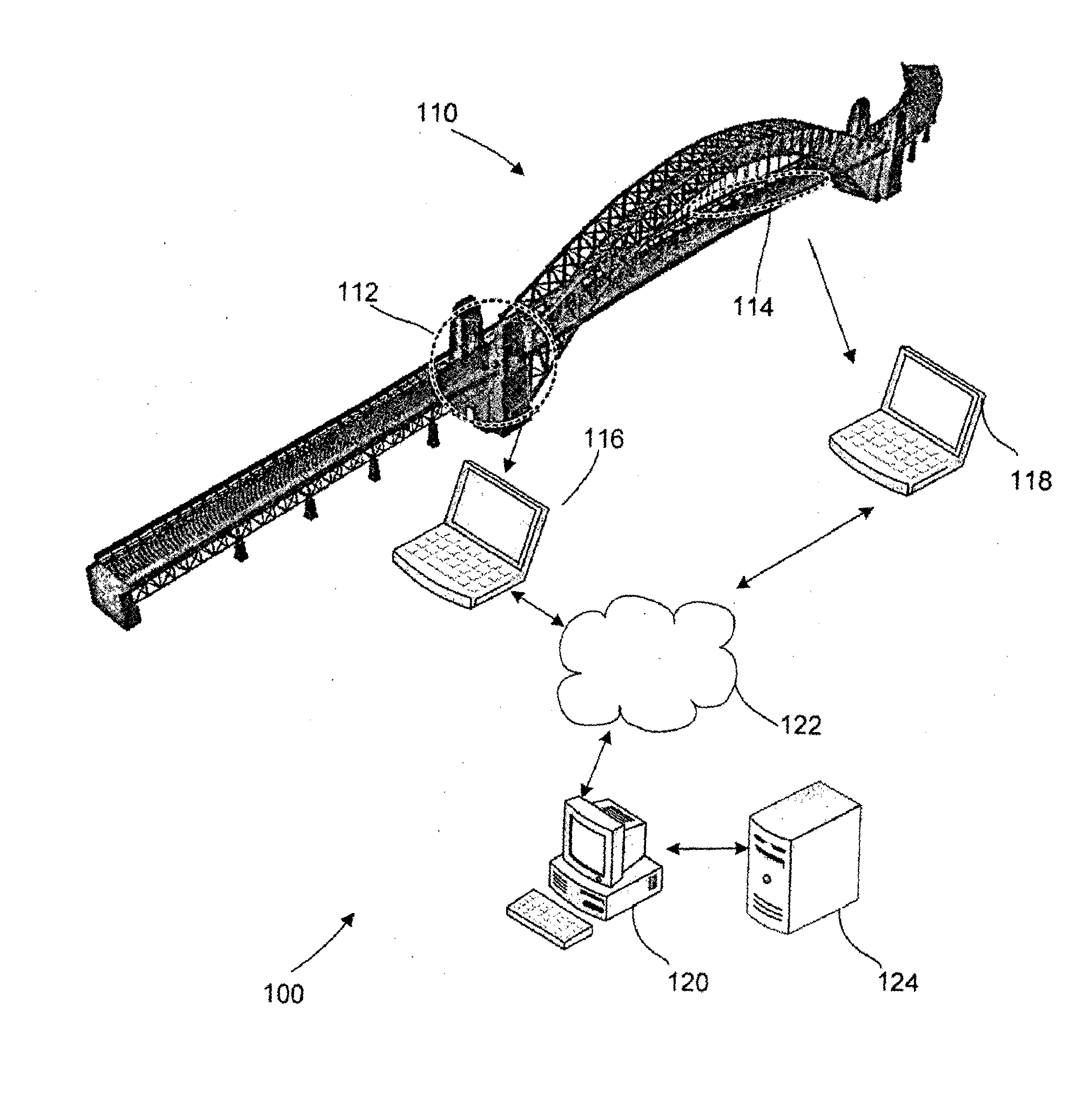
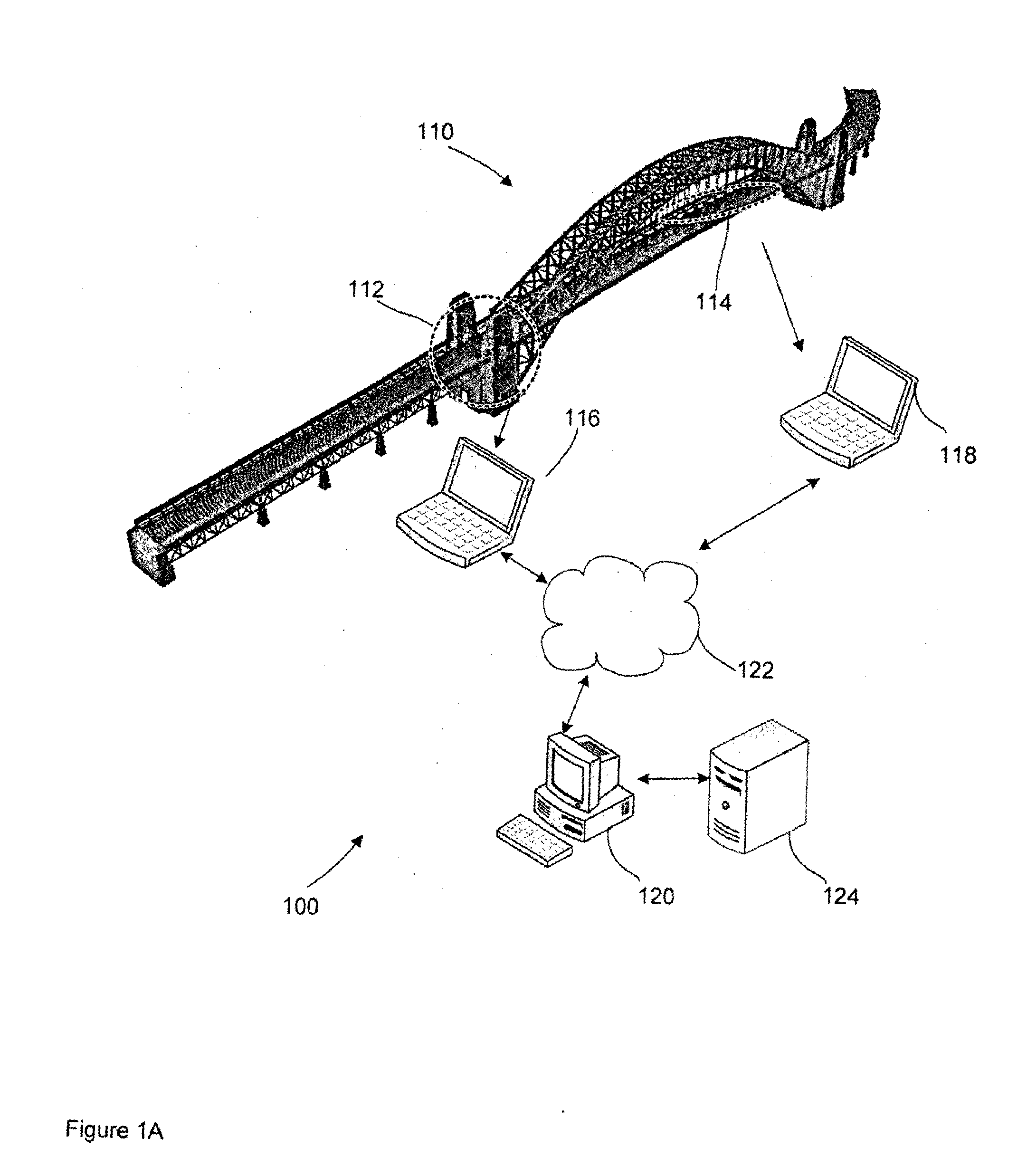
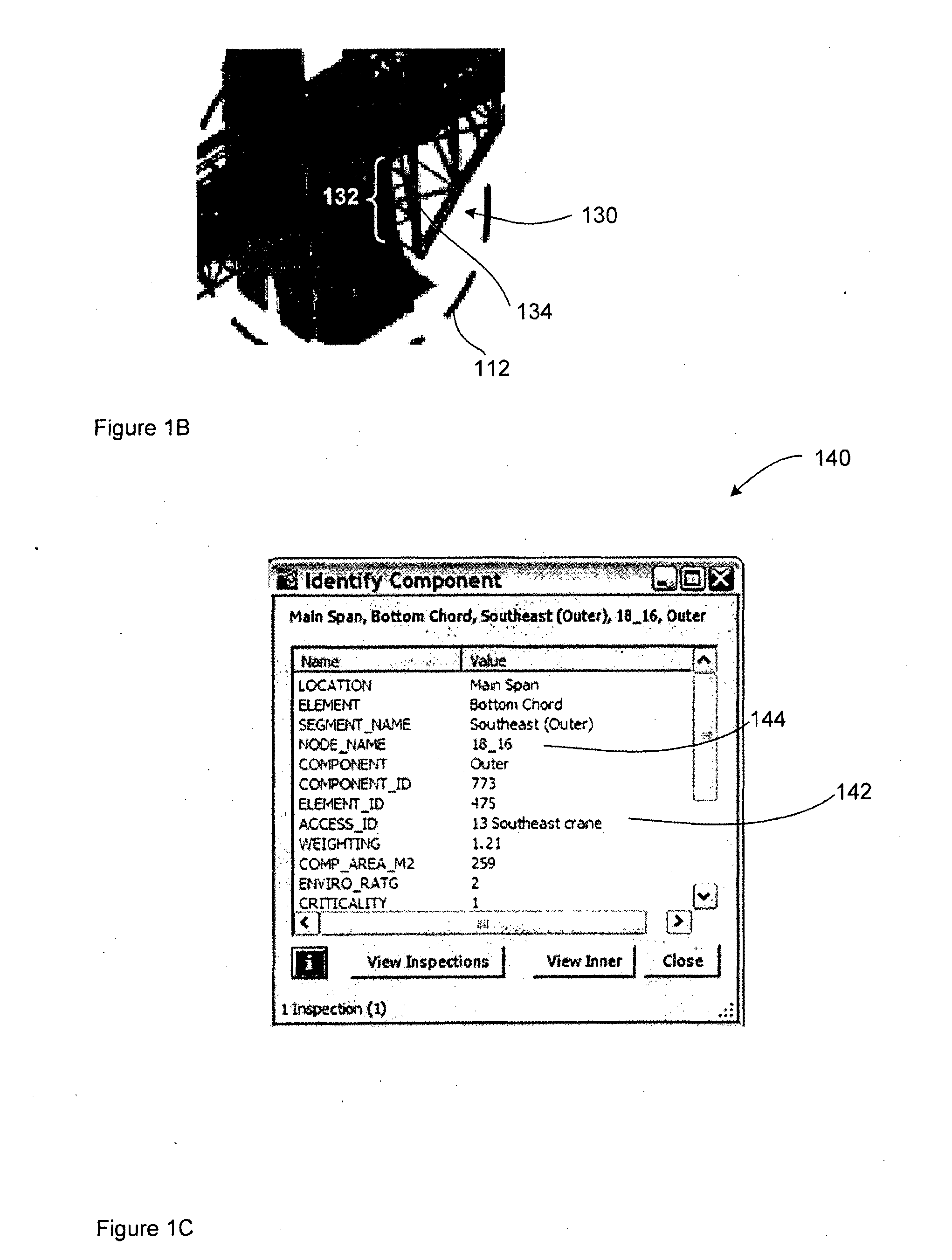
[0051]A maintenance system 100 for maintaining a complex structure is shown in FIG. 1A. The structure 110, a bridge in this case (the Sydney Harbour Bridge), consists of a plurality components. In this specification and accompanying claims a ‘component’ refers to the inspection unit for the structure 110 and a group of components is called a ‘segment’. An example of a component is the outer face 132 of the outer southeast segment 130 that forms part of the south pylon 112 of the bridge 110 as shown in FIG. 1B. A component includes one or more elements that require maintenance.

[0052]Large structures like bridges may have many thousands of components. Each component is characterised by one or more component features, and the maintenance system 100 maintains a record of the component features associated with each component. These component features are determined for the specific structure. An example of a component feature recorded for the outer face 132 is the...


PUM


Abstract

Embodiments of the invention generally relate to computational systems and methods for managing maintenance of a complex structure. A model of the structure is created and stored, which may be a 3D model of the structure including a 3D map, the model defined with reference to components of the complex structure. Maintenance parameters associated with the components are also stored. Examples of possible maintenance parameters include condition rating, criticality rating, access method and cost. Inspection data is input and received by the computational system. A maintenance plan is generated dependent on the maintenance parameters and the inspection data. The model is displayable as part of a 3D map provides a visual representation of information relating to the structure, which may include aspects of the inspection data, the maintenance parameters and the maintenance plan. Embodiments of the invention also relate to a computational system and method for managing maintenance of a painted or coated structure. A paint or coating condition model for at least one element of the structure has a deterioration that progresses as a function of x4, where x is the proportion of the life span of paint or coating that has elapsed. Based on this model a maintenance plan of proposed maintenance is generated and output.

Description

FIELD OF THE INVENTION[0001]The invention generally relates to the field of computer assisted modelling of structures and to the field of computer assisted scheduling of maintenance activities in relation to a structure.BACKGROUND OF THE INVENTION[0002]The maintenance of structures is an ongoing and resource intensive activity. It is therefore necessary to carefully plan and implement maintenance activities. The cost of a deficient maintenance program can be very high, and may result in early replacement of the structure or of expensive component parts of the structure. In addition, a deficient maintenance program may reduce the aesthetic appeal of buildings or iconic structures.[0003]The identification and scheduling of maintenance activities is assisted by the use of computers. Computer systems allow for the storage and retrieval of information regarding a structure and the maintenance performed on that structure, as well as providing tools for prompting maintenance actions. Howev...

Claims


Application Information

Patent Timeline
Patent Type & Authority Applications(United States)
IPC IPC(8): G06Q10/00G06F17/50
CPCG06F17/5004G06Q10/20G06Q10/10G06F30/13
Inventor MANN, PETER NOELMCGLYNN, JOHN MATHEW
Owner ROADS AND MARITIME SERVICES
Learn More