
Three-dimensional neural probe microelectrode array and method of manufacture

a microelectrode array and three-dimensional technology, applied in the field of three-dimensional neural probe microelectrode array and manufacturing method, can solve the problems of limited ability of commercial electrode array to position electrode contacts in a two-dimensional plan

Active Publication Date: 2015-05-14
SAPIENS STEERING BRAIN STIMULATION
View PDF1 Cites 5 Cited by
  • Summary
  • Abstract
  • Description
  • Claims
  • Application Information

AI Technical Summary

Benefits of technology

The present invention describes a method of creating a three-dimensional electrode tissue interface using multiple neural probe electrode arrays consisting of two or more planar probes arranged in side-by-side electrically connected to flexible ribbon cables. This allows for a more diverse and accurate stimulation or sensing of neural tissue. The method is scalable and customizable with regards to the geometry, size, and number of electrode contacts. Overall, the invention provides greater tolerance in positioning and the ability to connect with multiple neurons in the cortex and facilitate their functions.

Problems solved by technology

Commercially available electrode arrays are limited in their ability to position electrode contacts in a three-dimensional arrangement.
The Michigan Probe is limited to positioning electrode contacts in a two-dimensional arrangement, all within a single plane.
The Utah Array is also limited to positioning electrode contacts in a two-dimensional plane.
Moreover, electrode contacts in a Utah Array are limited to placement on the tip of each electrode shank.

Method used


Image

  • Three-dimensional neural probe microelectrode array and method of manufacture
  • Three-dimensional neural probe microelectrode array and method of manufacture
  • Three-dimensional neural probe microelectrode array and method of manufacture

Examples


Embodiment Construction

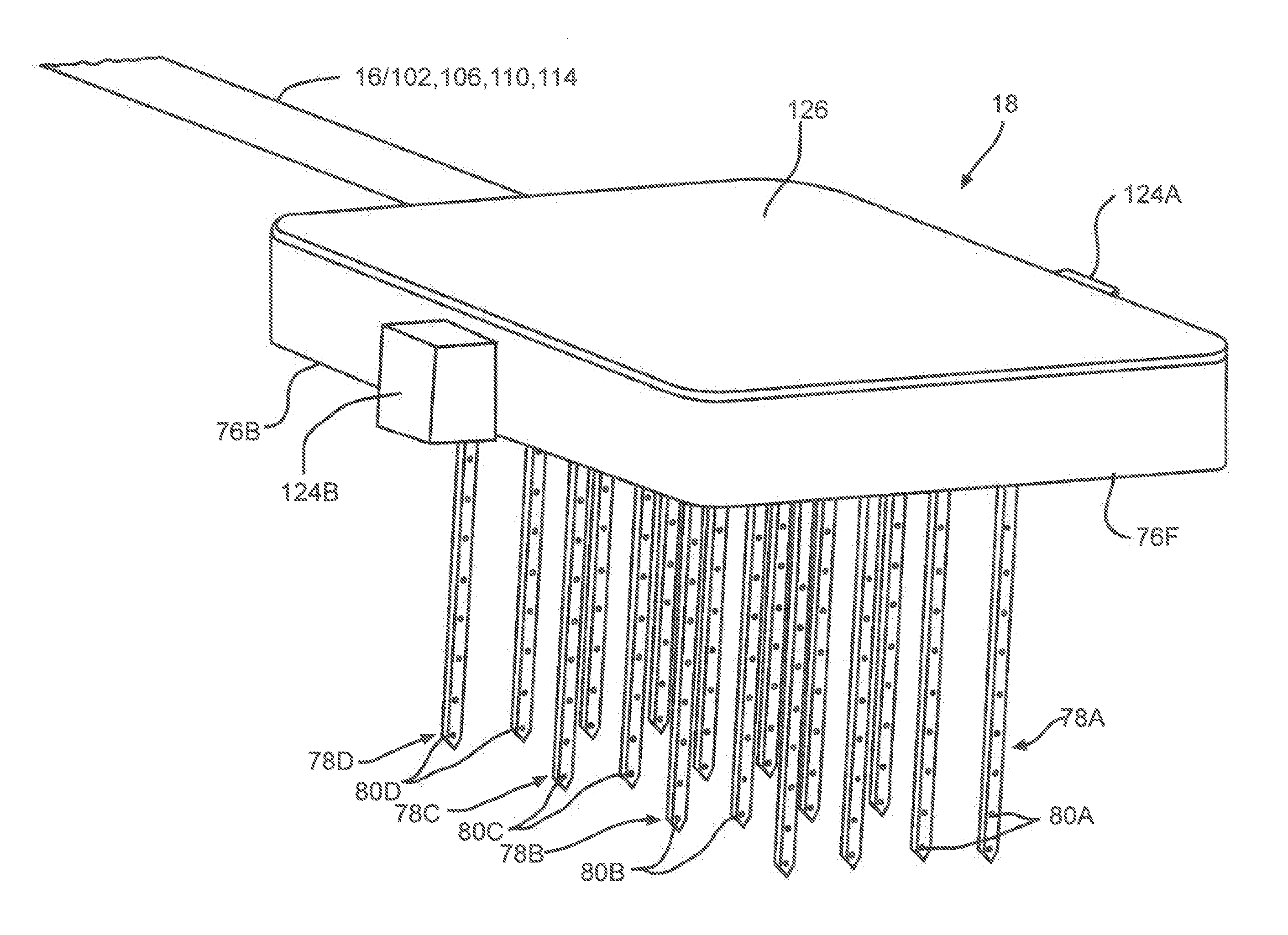
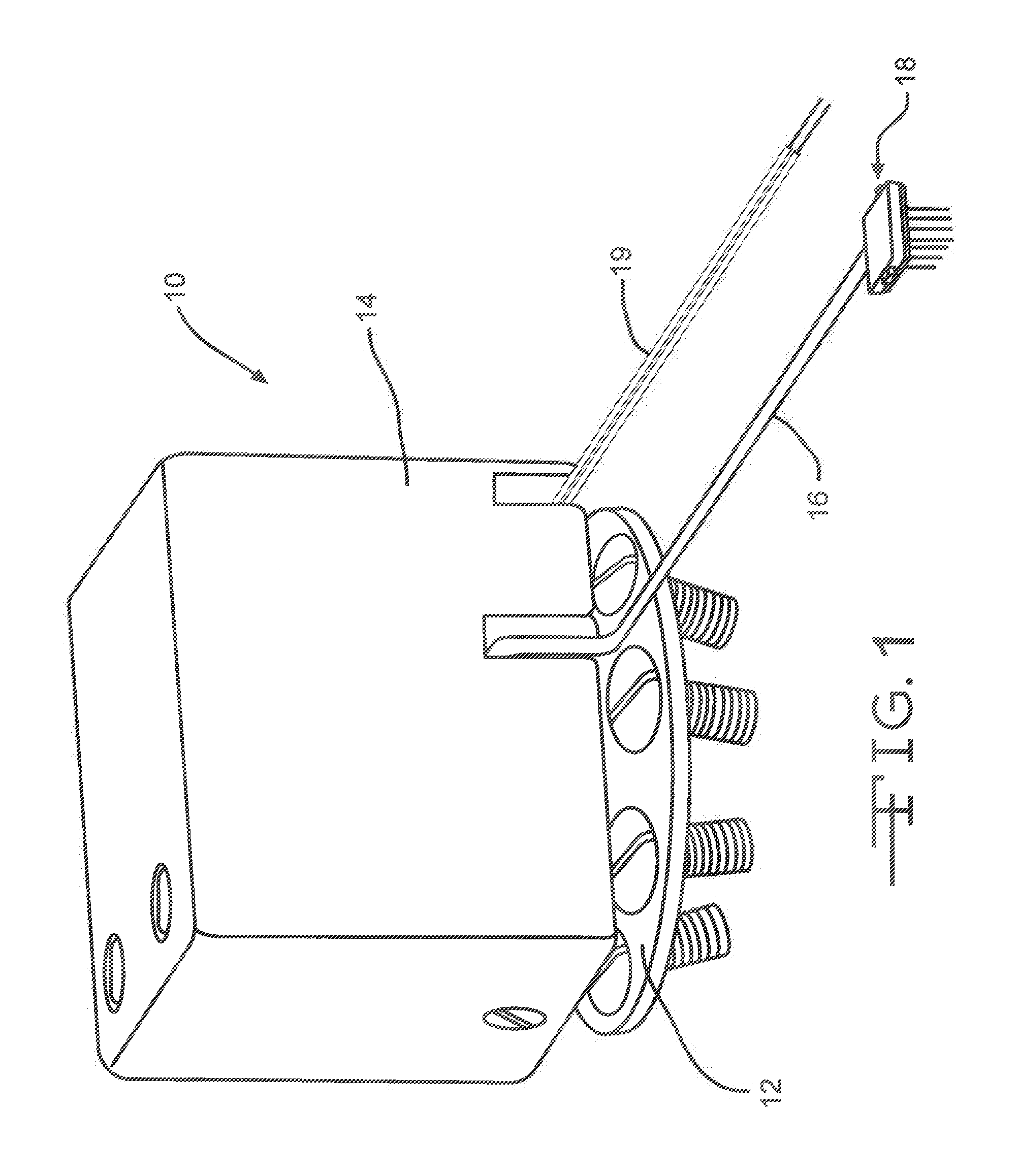
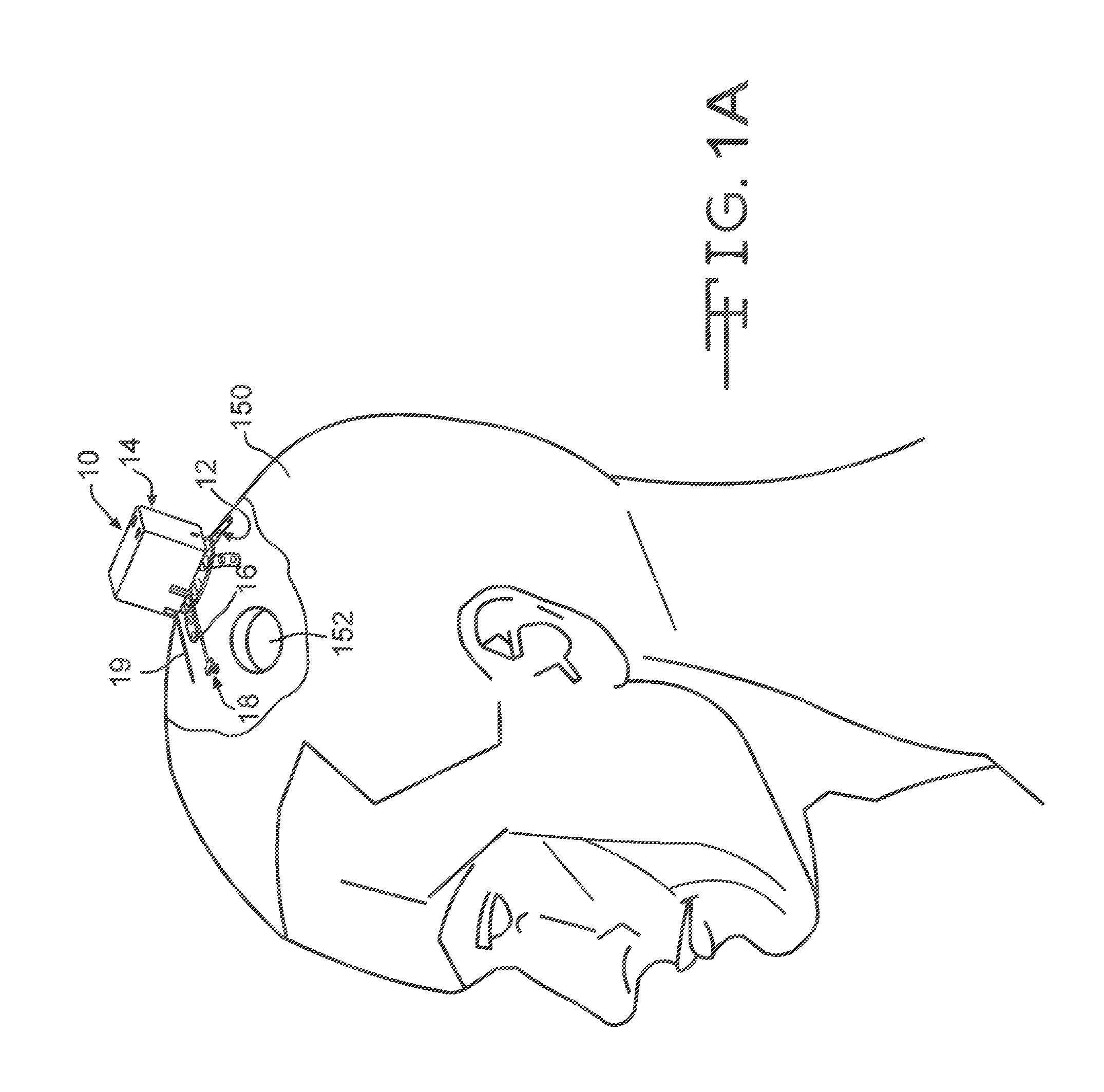
[0027]Turning now to the drawings, FIG. 1 is a perspective view of a neural probe electrode array system 10 according to the present invention. The neural probe system 10 comprises a skull mounting plate 12 supporting an electronics housing 14. A flexible ribbon cable 16 connects from electronics (see connectors 134A to 134D in FIGS. 15 and 16) in the housing 14 to a neural probe electrode assembly 18. A neural probe electrode assembly 18 according to the present invention includes at least one, and preferably a plurality of neural probe electrode arrays as exemplified in FIGS. 5 and 6. The housing 14 further includes wires 19 for grounding the subject. These wires not only ground the animal, but may be used as a reference when performing differential recording, or as a return path for current when stimulating.

[0028]FIG. 2 illustrates the skull mounting plate 12 comprising a curved mount body 20 supporting a plurality of extending legs 22. The curved body 20 is a dome-shaped member ...


PUM

PropertyMeasurementUnit
Thicknessaaaaaaaaaa
Thicknessaaaaaaaaaa
Thicknessaaaaaaaaaa

Abstract

A three-dimensional neural probe electrode array system is described. Planar probes are microfabricated and electrically connected to flexible micro-machined ribbon cables using a rivet bonding technique. The distal end of each cable is connected to a probe with the proximal end of the cable being customized for connection to a printed circuit board. Final assembly consists of combining multiple such assemblies into a single structure. Each of the two-dimensional neural probe arrays is positioned into a micro-machined platform that provides mechanical support and alignment for each array. Lastly, a micro-machined cap is placed on top of each neural electrode probe and cable assembly to protect them from damage during shipping and subsequent use. The cap provides a relatively planar surface for attachment of a computer controlled inserter for precise insertion into the tissue.

Description

CROSS-REFERENCE TO RELATED APPLICATIONS[0001]This application claims priority from U.S. Provisional Application Ser. Nos. 61 / 901,783, filed on Nov. 8, 2013.BACKGROUND OF THE INVENTION[0002]1. Field of the Invention[0003]The invention relates to the field of devices and methods used for neural interventions.[0004]2. Prior Art[0005]The conventional method used to interface the nervous system includes a multi-contact electrode array. Electrode arrays are designed to transmit signals into the tissue (“stimulation”) or extract signals from the tissue (“sense”). These electrode arrays are commonly used in neuroscience and neurophysiological research as well as in clinical therapeutic applications. Often, a precise volume of tissue in the peripheral nervous system or in the central nervous system is the target for placement of the electrode array. Additionally, it is desirable to interface with the targeted volume in three-dimensions. Commercially available electrode arrays are limited in ...

Claims


Application Information

Patent Timeline
IPC IPC(8): A61N1/05H01R43/26
CPCH01R43/26A61N1/0529A61N1/0539Y10T29/49169A61B5/6868A61B5/6882A61B5/24A61B5/291A61B5/293A61N1/0456A61N1/0472
Inventor VETTER, RIO J.HETKE, JAMILLE FARRAYEPELLINEN, DAVID S.SUWARATO, BENCHARONGKONG, KC
Owner SAPIENS STEERING BRAIN STIMULATION
Learn More