
LED actuating device and method

Active Publication Date: 2015-05-07
HU JUN
View PDF4 Cites 2 Cited by
  • Summary
  • Abstract
  • Description
  • Claims
  • Application Information

AI Technical Summary

Benefits of technology

The invention is a LED lamp that detects its temperature and voltage to adjust the amount of electricity it uses, reducing the chances of overheating and increasing its lifespan. This results in the LED lamp operating at a lower temperature and reducing energy consumption.

Problems solved by technology

If the value is exceeded, the LED becomes hot and can be damaged.
If the value is exceeded, diodes can be damaged.
If the value is exceeded, the light-emitting diode can be broken down and damaged.
No matter under numerical control or simulation control, when a constant-current and constant-voltage LED actuating power supply is equipped to actuate the LED lamp unit, the constant-voltage or constant-current control technology is adopted during operation no matter how great the VF value of the LED lamp unit is changed, that is, the output voltage and current coincide with the rated values of the lamp unit; however, the VF-values of LED lamp units are different from those of different manufacturers, especially the VF-value consistency is much poorer for the LED lamp units from those of the factories with a less advanced packaging technology.
And after lamp beads completely different in the VF-value consistency constitute a lamp unit, the VF-values quickly drift and decrease under the impact of the temperature, but the existing LED power supplies all have constant voltage or constant current, so it is completely impossible to adjust the output current and voltage according to the serious drift of the VF-value when the LED lamp unit is exposed to a high temperature, thus forcing the LED lamp unit to operate under the condition of low VF voltage and constant current.

Method used


Image

  • LED actuating device and method
  • LED actuating device and method
  • LED actuating device and method

Examples


Embodiment Construction

[0026]The technical solutions in the embodiments of the invention are described clearly and completely in conjunction with the figures attached in the embodiments, and obviously, the described embodiments are only part of, rather than all of embodiments in the invention. Based on the embodiments in the invention, all other embodiments obtained at the premise of no creativity made by a person skilled in the part are all within the protection scope of the invention.

[0027]The invention can be used for detecting the VF-value of the LED lamp unit dynamically, then the corresponding actuating current is matched with the LED lamp unit according to the decrease of the luminous flux resulting from the VF-value changes, further the LED actuating current is adjusted dynamically to save energy and prolong the service life of the LED lamp unit. The invention is described in details further by virtue of the figures attached.

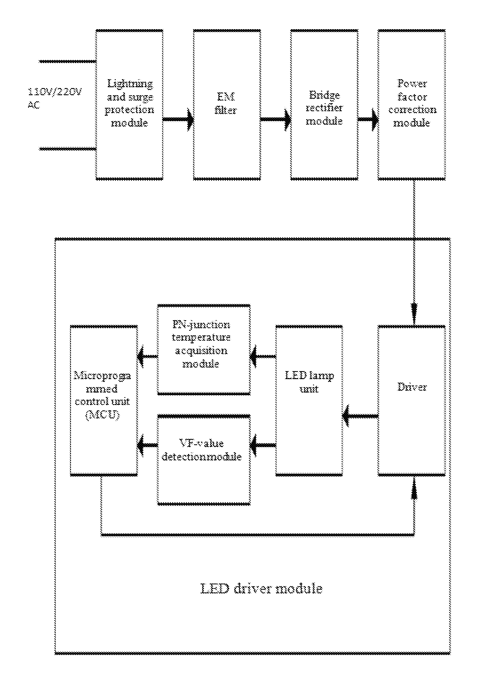
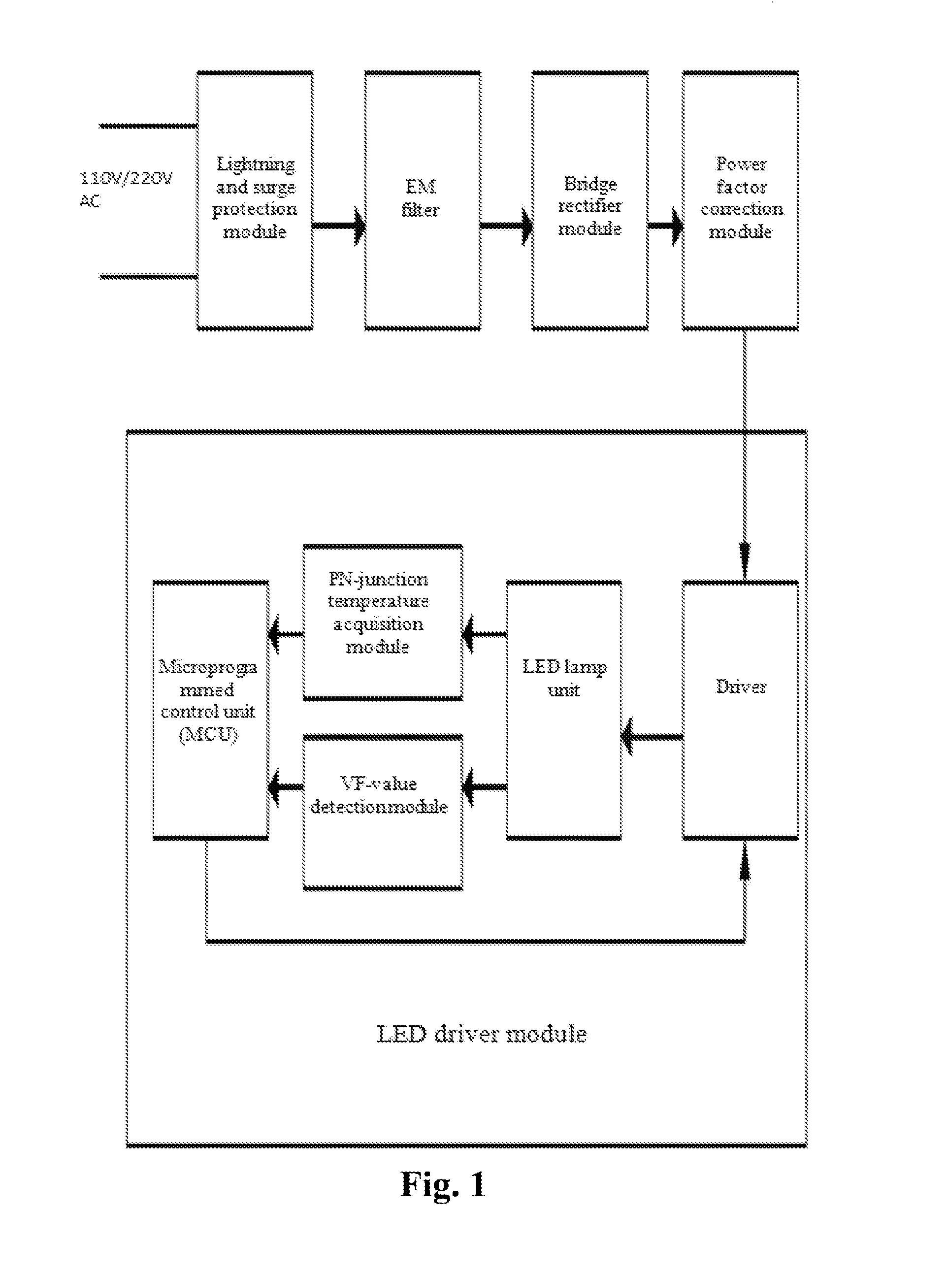
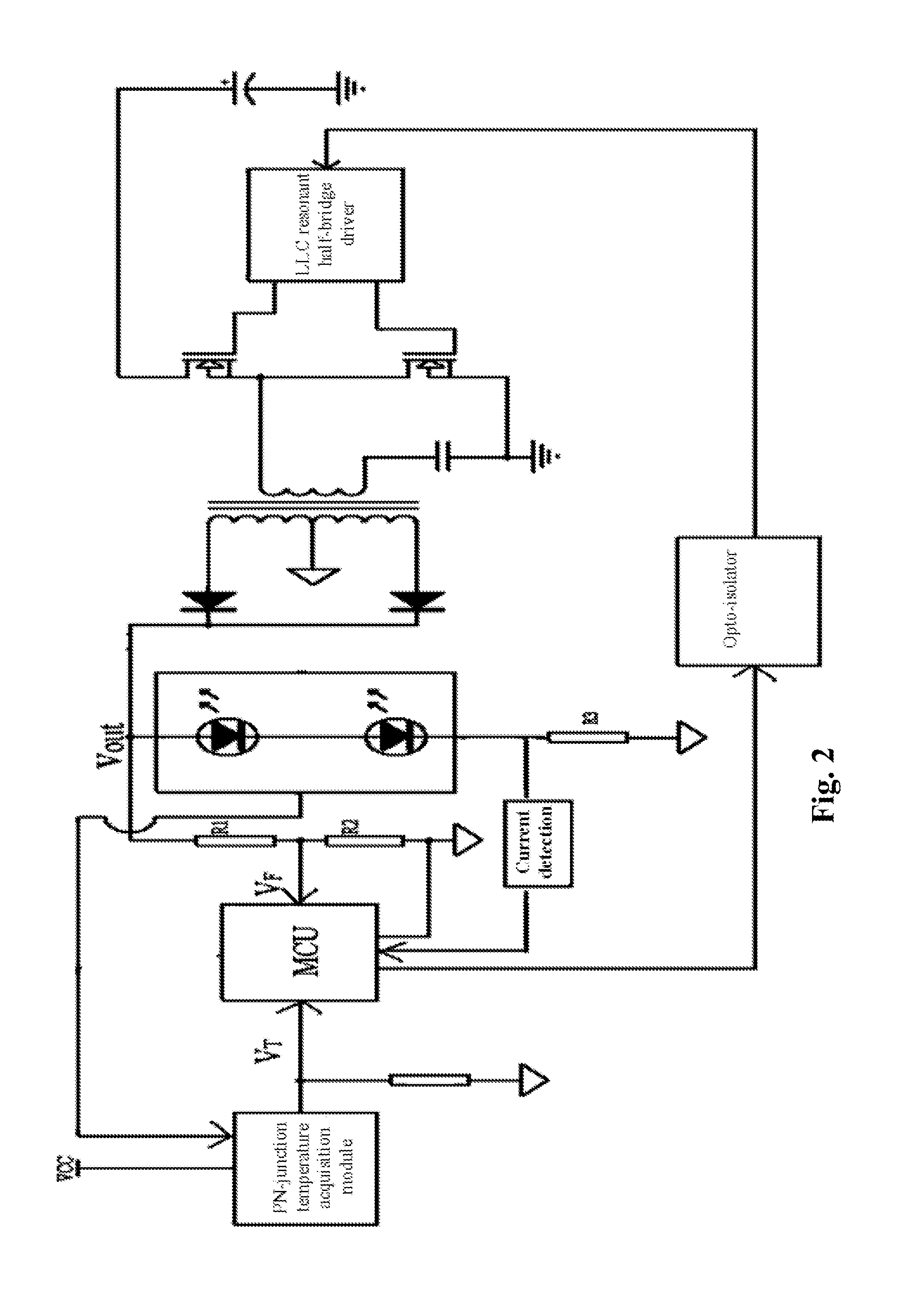
[0028]FIG. 1 is a schematic diagram of the embodiment of the LED lamp uni...


PUM


Abstract

An actuating device comprises an LED actuating module. Said LED actuating module comprises a micro-programmed control unit (MCU), an actuator, a VF-value detection module, a PN-junction temperature acquisition module and an LED lamp unit. The MCU determines the current value matched with the LED lamp unit based on the VF value detected by the VF-value detection module and the temperature value detected by the PN-junction temperature acquisition module, and then determines the width of the PWM pulse output to the actuator according to the current value, and the actuator actuates an LED to operate at the matched current value.

Description

FIELD OF THE INVENTION[0001]The invention relates to illumination, and particularly relates to an LED actuating device and method.BACKGROUND OF THE INVENTION[0002]An LED semiconductor luminescent device comprises a semiconductor light-emitting diode (LED), a nixie tube, a symbol tube, a *-shaped tube and a dot matrix display screen (hereinafter referred to as a “matrix tube”) and the like. In fact, each light-emitting unit in the nixie tube, the symbol tube, the *-shaped tube and the matrix tube is a light-emitting diode.[0003]The performance of an LED is determined by parameters of the LED and some key parameters relevant to an LED are as follows: (1) allowable power dissipation Pm, which refers to the maximum value of the product of the forward DC voltage allowed to be applied on both ends of the LED and the passing-through current. If the value is exceeded, the LED becomes hot and can be damaged. (2) Maximum forward DC current IFm, which refers to the allowable maximum forward DC...

Claims


Application Information

Patent Timeline
IPC IPC(8): H05B33/08H05B44/00
CPCH05B33/0815H05B33/0842H05B45/39H05B45/14H05B45/18H05B45/382H05B45/38
Inventor HU, JUNDENG, YONGMINGLIU, PING
Owner HU JUN
Learn More