Portable electronic device

a technology of electronic devices and portability, applied in the field of portable electronic devices, can solve the problems of easy deterioration of the sensor electrode, and low degree of freedom in the attachment position, and achieve the effect of improving the product li

Active Publication Date: 2015-04-30
SEIKO INSTR INC
View PDF15 Cites 9 Cited by
  • Summary
  • Abstract
  • Description
  • Claims
  • Application Information

AI Technical Summary

Benefits of technology

The present invention aims to provide a portable electronic device that can increase its lifespan and can be attached to any position.

Problems solved by technology

However, in the structures disclosed in Patent Literatures 1 and 2, the sensor electrode is easily deteriorated by washing of the garment or the like as the sensor electrode is attached to the garment.
Therefore, the sensor electrode is not always arranged in an appropriate position with respect to the body in the state where the garment is worn on the body due to the individual difference even when the user selects the garment in the appropriate size for the user's body.
Additionally, as the sensor electrode is previously provided in the garment, it is difficult to adjust the position of the sensor electrode so as to correspond to the user, therefore, the degree of freedom in the attachment position is low.
Therefore, there is a danger that detection performance in the sensor electrode is reduced when the position of the sensor electrode is inappropriate.
The position of the sensor electrode may give uncomfortable feeling to the user in the state where the user puts on the sensor, which may cause a problem in wearing feeling.
Also in this case, the above-described problems exist in common.

Method used


Image

  • Portable electronic device
  • Portable electronic device
  • Portable electronic device

Examples


first embodiment

[0048]Next, a first embodiment of the present invention will be explained with reference to the drawings.

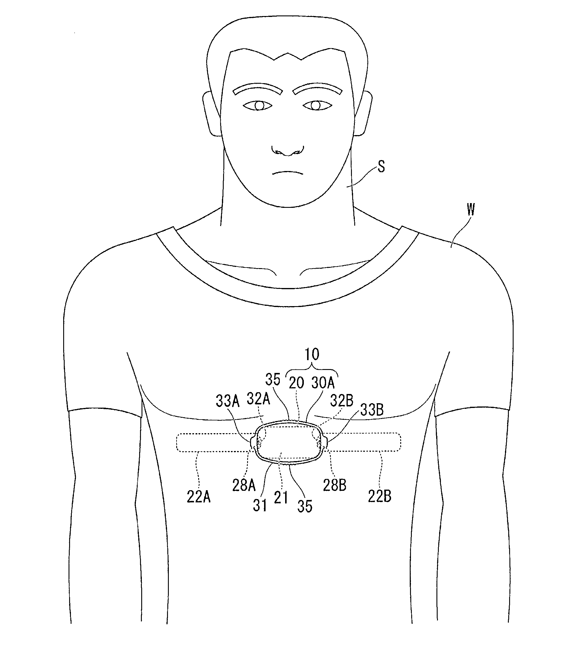
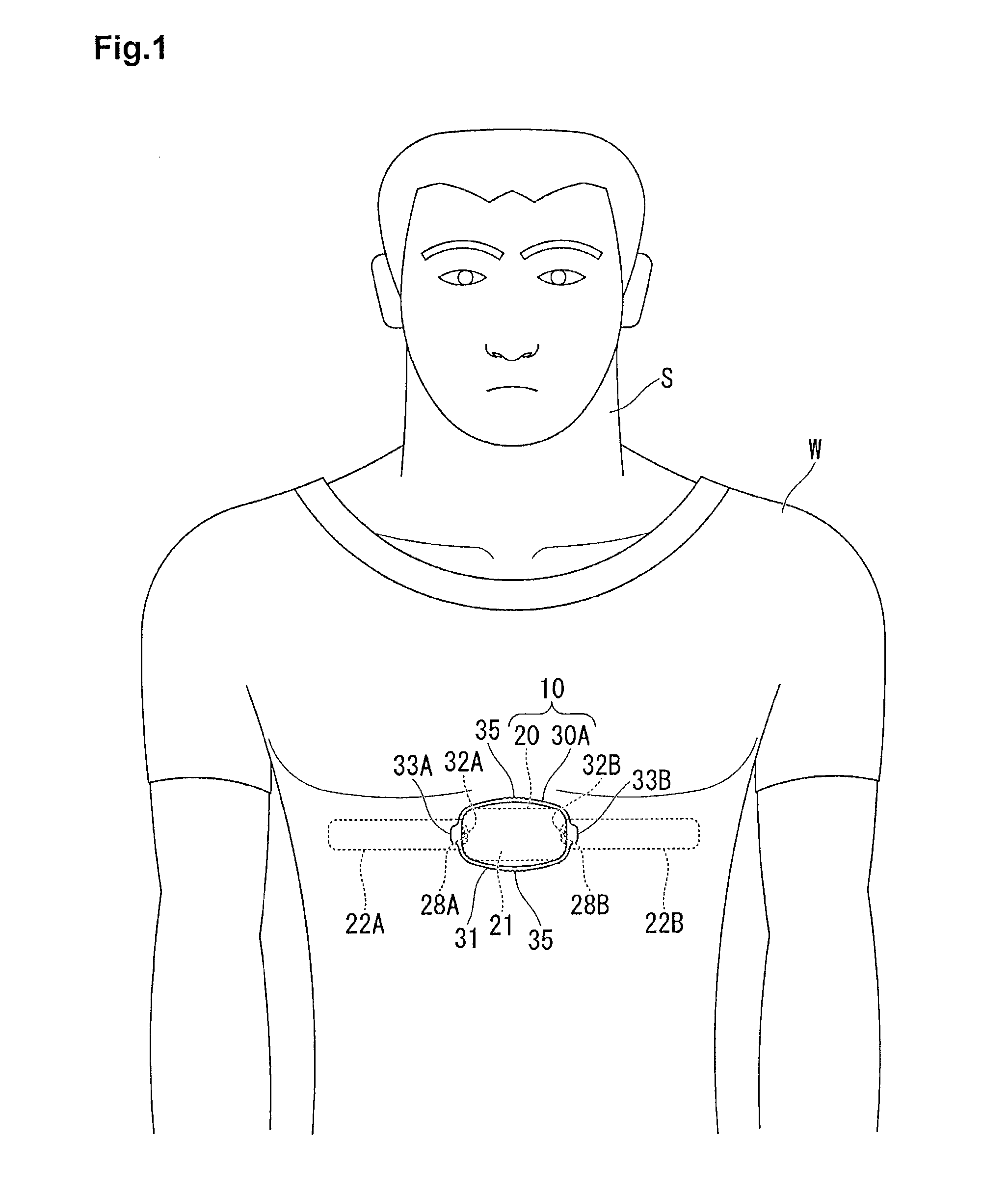
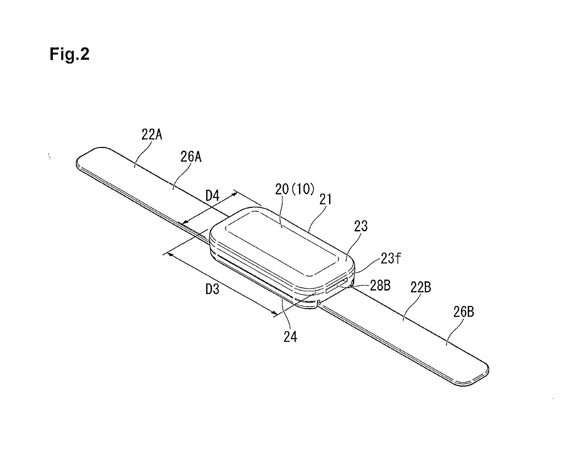
[0049]FIG. 1 is a front view showing a state where a heart rate measuring device as a portable electronic device according to the present invention is attached to a user, and FIG. 2 is a perspective view showing a device body included in the heart rate measuring device.

[0050]As shown in FIG. 1, a heart rate measuring device (corresponding to a “portable electronic device” in claims) 10 detects an electrocardiographic signal generated by heartbeats by being attached to a chest as a biological surface of a user S, and transmits the detected electrocardiographic signal by wireless communication.

[0051]The heart rate measuring device 10 includes a device body 20 and a fixing member 30A for attaching the device body 20 to a garment W worn by the user S.

[0052]As shown in FIG. 1 and FIG. 2, the device body 20 includes a case 21 formed in a rectangular shape in planar view, a not-shown de...

second embodiment

[0092]FIG. 9 is a front view showing a heart rage measuring device as a portable electronic device according to a second embodiment of the present invention. FIG. 10 is a perspective view of a fixing member included in the heart rate measuring device.

[0093]Next, the portable electronic device according to the second embodiment of the present invention will be explained.

[0094]In the first embodiment, the fixing member 30A is formed in the ring shape (see FIG. 1).

[0095]Whereas, the second embodiment differs from the first embodiment in a point that a fixing member 30B is formed to have a cross shape in a front view as shown in FIG. 9. In the second embodiment described below, the components common to the first embodiment are denoted by the same reference numerals and signs in the drawing, and the explanation thereof is omitted.

[0096]As shown in FIG. 9 and FIG. 10, the heart rate measuring device 10 includes the device body 20 having the same structure as the first embodiment and the f...

first modification example of second embodiment

[0107]Next, respective modification examples of the second embodiment will be described. In the above second embodiment, the fixing member 30B is formed so that the first band-shaped portion 36 and the second band-shaped portion 37 make the cross shape, however, the present invention is not limited to this.

[0108]FIG. 11 is a front view showing a heart rate measuring device as a first modification example of the second embodiment of the present invention. FIG. 12 is a perspective view of a fixing member included in the heart rate measuring device. FIG. 13 is a cross-sectional view taken along X-X line of FIG. 11.

[0109]For example, as shown in FIG. 11 to FIG. 13, a fixing member 30C has an X-shape in a state of being attached to the device body 20, including a first band-shaped portion (corresponding to a “protective portion” in claims) 45 and a second band-shaped portion (protective portion) 46 which extend in diagonal directions of the device body 20.

[0110]Then, both end portions of...


PUM


Abstract

To improve product lifetime as well as to increase wearing feeling, maintainability and productivity, and to suppress manufacturing costs and expenses of the user. A portable electronic device 10 includes a device body 20 arranged inside a garment W and housing an electronic component and a fixing member 30A formed separately from the device body 20 and arranged outside the garment W, which fixes the device body 20 so as to be attached and detached to and from the garment W in a state of sandwiching the garment W between the fixing member 30A and the device bogy 20 from the other side of the garment W. The fixing member 30A is formed so as to be elastically deformed, which is formed in a ring shape surrounding the device body 20. Gaps are provided on both sides of the device body 20 in the radial direction of the fixing member 30A between an inner peripheral surface of the fixing member 30A and the device body 20.

Description

RELATED APPLICATIONS[0001]This application claims priority under 35 U.S.C. §119 to Japanese Patent Application No. 2013-222410 filed on Oct. 25, 2013, the entire content of which is hereby incorporated by reference.BACKGROUND OF THE INVENTION[0002]1. Field of the Invention[0003]The present invention relates to a portable electronic device.[0004]2. Description of the Related Art[0005]There exist biological information detecting devices detecting a biological signal by attaching a sensor electrode to a biological surface. In this kind of biological information detecting devices, there is the one which measures a heart rate from the biological surface, for example, by detecting an electrocardiographic signal generated by heartbeats by the sensor electrode. As such a biological information detecting device, for example, there is the one which includes a sensor electrode and a device body (transmission unit) transmitting an electrocardiographic signal detected by the sensor electrode to ...

Claims


Application Information

Patent Timeline
IPC IPC(8): A61B5/00A61B5/0245A41D1/00A61B5/332
CPCA61B5/6804A61B5/0245A41D1/002A41D13/1281A61B5/02438A61B5/6831A61B5/0006A61B5/25A61B5/282A61B5/256A61B5/28
Inventor OKUDA, HIDEKITERASAWA, DAIKATO, TERUO
Owner SEIKO INSTR INC
Why Eureka
Try Eureka