
Radio communication system, radio base station, and communication control method

a radio base station and communication control technology, applied in the direction of digital transmission, wireless commuication services, transmission path sub-channel allocation, etc., can solve the problems of high interference levels of mobile terminals located at the edges of cells of small power base stations, and the excessive communication load thereon, so as to improve the reception quality of mobile terminals

Inactive Publication Date: 2015-04-30
NTT DOCOMO INC
View PDF3 Cites 12 Cited by
  • Summary
  • Abstract
  • Description
  • Claims
  • Application Information

AI Technical Summary

Benefits of technology

The present invention relates to a radio communication system that uses eICIC for interference control between large power base stations and small power base stations. The invention proposes a method to improve the reception quality of mobile terminals and control signals by adjusting the proportion of available resources for the large power base station based on the proportion of mobile terminals capable of interference rejection and traffic demands. By doing so, the mobile terminals at the edges of the small power base stations can improve their reception quality without sacrificing the quality of broadcast and control signals. Additionally, the invention suggests transmitting all types of broadcast and control signals used in the small power base stations to the large power base station and improving the certainty of mobile terminals to receive these signals during handover. This improves the overall quality of the network.

Problems solved by technology

Therefore, it is assumed that connections from user terminals are concentrated at a base station of large transmitted power, which in turn makes the communication load thereon tend to become excessive.
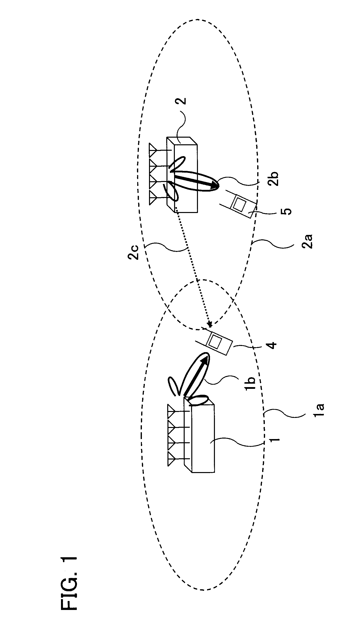
However, when the cell ranges of the small power base stations are expanded by the cell range expansion (CRE), mobile terminals located at the edges of the cells of the small power base stations may be subject to high levels of interference by the radio waves from neighboring macro base stations.
However, the macro base station can perform the downlink transmission only intermittently.

Method used


Image

  • Radio communication system, radio base station, and communication control method
  • Radio communication system, radio base station, and communication control method
  • Radio communication system, radio base station, and communication control method

Examples


first embodiment

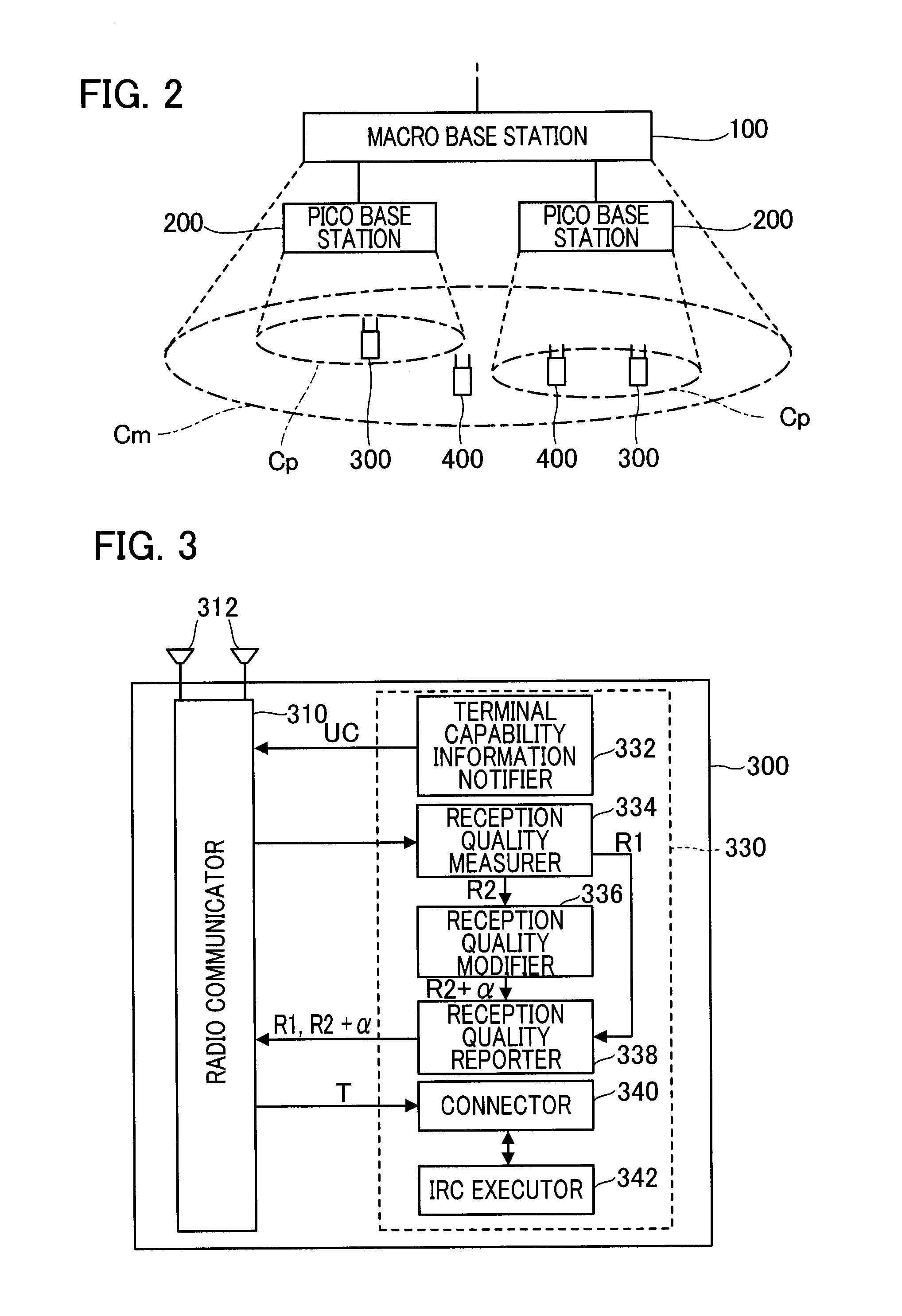
[0057]FIG. 2 is a block diagram of a radio communication system according to the first embodiment of the present invention. This radio communication system has a macro base station (macro eNodeB (evolved Node B)) 100, pico base stations 200, IRC terminals 300 (UE, User Equipment) which are mobile terminals capable of executing the interference rejection combining (IRC) and non-IRC terminals 400 which are mobile terminals incapable of the interference rejection combining. In this embodiment, the pico base stations 200 are Remote Radio Heads (RRH). In the following description, the IRC terminal 300 and the non-IRC terminal 400 are sometimes referred to as a “user terminal” without distinguishing therebetween.

[0058]Each of the communication elements (the macro base station 100, the pico base stations 200, the IRC terminals 300, the non-IRC terminals 400, etc.) in the radio communication system performs radio communication according to a predetermined Radio Access Technology, e.g., the ...

second embodiment

[0110]In the first embodiment, the resource setter 134 of the macro base station 100 sets the number of protected subframes PSF in the radio frame F based on the proportion of the number of the IRC terminals 300 to the total number of user terminals connecting to the pico base stations 200. However, in the second embodiment, the resource setter 134 may set the number of protected subframes PSF in the radio frame F based on the traffic of the IRC terminals 300 to the total traffic of user terminals connecting to the pico base stations 200.

[0111]In the second embodiment, the configurations of the macro base station 100, the pico base stations 200, and the user terminal (the IRC terminal 300 and the non-IRC terminal 400) may be the same as those according to the first embodiment. The features that are the same as in the first embodiment will not be described here in detail. However, the following features are different.

[0112]The terminal capability determiner 232 (FIG. 6) of the contro...

third embodiment

[0119]In the above first embodiment, the resource setter 134 of the macro base station 100 sets the number of the protected subframes PSF in the radio frame F based on the proportion of the number of the IRC terminals 300 to the total number of user terminals connecting to the pico base stations 200. However, in the third embodiment, the resource setter 134 may set the number of protected subframes PSF in the radio frame F based on the number of the IRC terminals 300 to the total number of user terminals connecting to the macro base station 100.

[0120]In the third embodiment, the configuration of a user terminal (the IRC terminal 300 and the non-IRC terminal 400) may be the same as those according to the first embodiment. The features that are the same as in the first embodiment will not be described here in detail. However, as shown in FIG. 13, in the macro base station 100, the resource setter 134 sets the number of protected subframes PSF in the radio frame F based on a type of a ...


PUM


Abstract

Resources available for large power base stations are controlled in a radio communication system in which mobile terminals with and without interference suppression capability are used together and in which a large power base station and small power base stations coordinate inter-cell interference control. A radio base station coordinates inter-cell interference control with at least one second radio base station forming a second cell within a first cell of the radio base station, the second cell having a smaller area than the first cell. The radio base station has a resource setter for setting a ratio of a first resource in which the radio base station is to execute radio communication and a second resource in which the radio base station is to stop radio communication according to the ratio of the number of mobile terminals capable of executing interference rejection combining to the total number of mobile terminals connecting to the radio base station or to at least one second radio base station.

Description

FIELD OF THE INVENTION[0001]The present invention relates to a radio communication system, to a radio base station, and to a communication control method.BACKGROUND ART[0002]In LTE (Long Term Evolution) Advanced in the 3GPP (Third Generation Partnership Project), OFDMA (Orthogonal Frequency Division Multiplexing Access) using MU-MIMO (multi-user multiple-input multiple-output) has been proposed. In the downlink transmission of MU-MIMO, one base station communicates not only with multiple mobile terminals (UE, user equipments), but also can transmit different data streams (layers) to one mobile terminal simultaneously.[0003]In the LTE Advanced, a reception technology of the mobile terminal called Interference Rejection Combining is under consideration. The Interference Rejection Combining (IRC) is a technique to give weightings to signals obtained by respective reception antennas at a mobile terminal so as to suppress, at the mobile terminal, the interference of an interference radio...

Claims


Application Information

Patent Timeline
IPC IPC(8): H04L5/00H04W72/08
CPCH04W72/082H04L5/0032H04W52/04H04W8/24H04W48/20H04W16/10H04W16/32H04W72/51H04W72/541
Inventor OHWATARI, YUSUKEMIKI, NOBUHIKOMORIMOTO, AKIHITOOKUMURA, YUKIHIKO
Owner NTT DOCOMO INC
Learn More