
Waste gate assembly for turbocharger

a turbocharger and waste gate technology, applied in the direction of valve operating means/release devices, machines/engines, mechanical apparatus, etc., can solve the problem of difficult to actively control the discharge amount of exhaust gas, and achieve the effect of reducing the rattle of the turbocharger and preventing the cracking of the turbine housing

Inactive Publication Date: 2015-04-30
HYUNDAI MOTOR CO LTD +1
View PDF4 Cites 9 Cited by
  • Summary
  • Abstract
  • Description
  • Claims
  • Application Information

AI Technical Summary

Benefits of technology

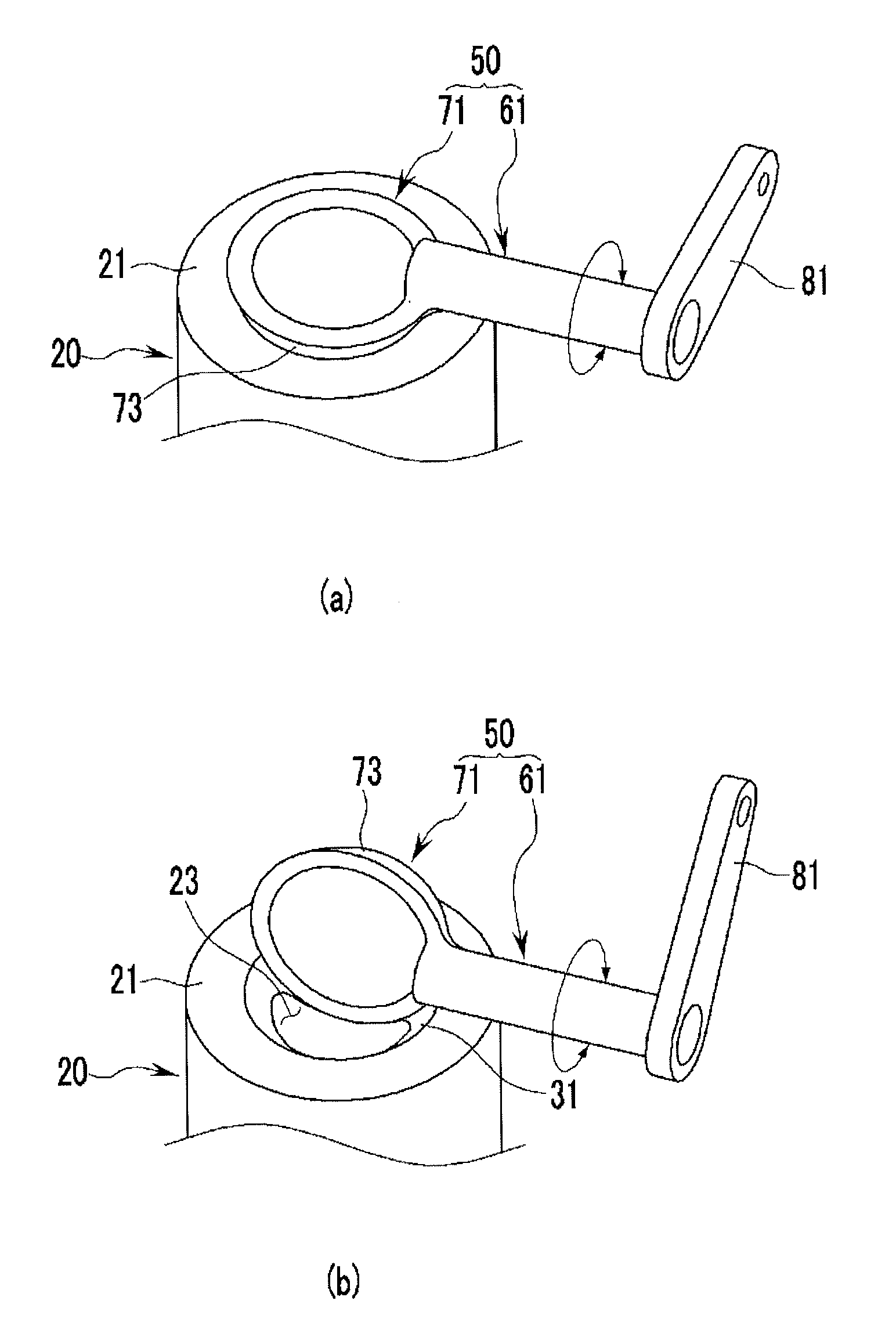
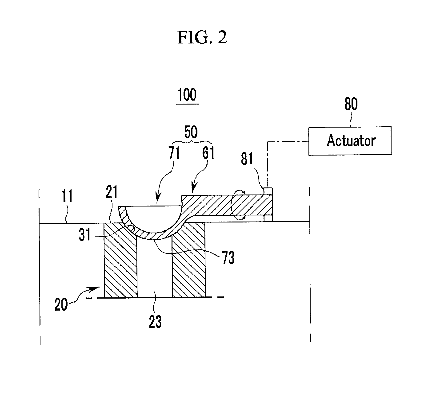
The present invention is a waste gate assembly for a turbocharger that has advantages of reducing rattle noise, preventing crack of the turbine housing, and actively controlling the discharge amount of exhaust gas. The valve is designed to be slidably rotated through the spherical portion with respect to the spherical groove of the boss, which reduces rattle noise and prevents crack of the turbine housing. The valve is also designed to be opened or closed by a small driving power of an actuator, which reduces wear of the valve and expands lifespan.

Problems solved by technology

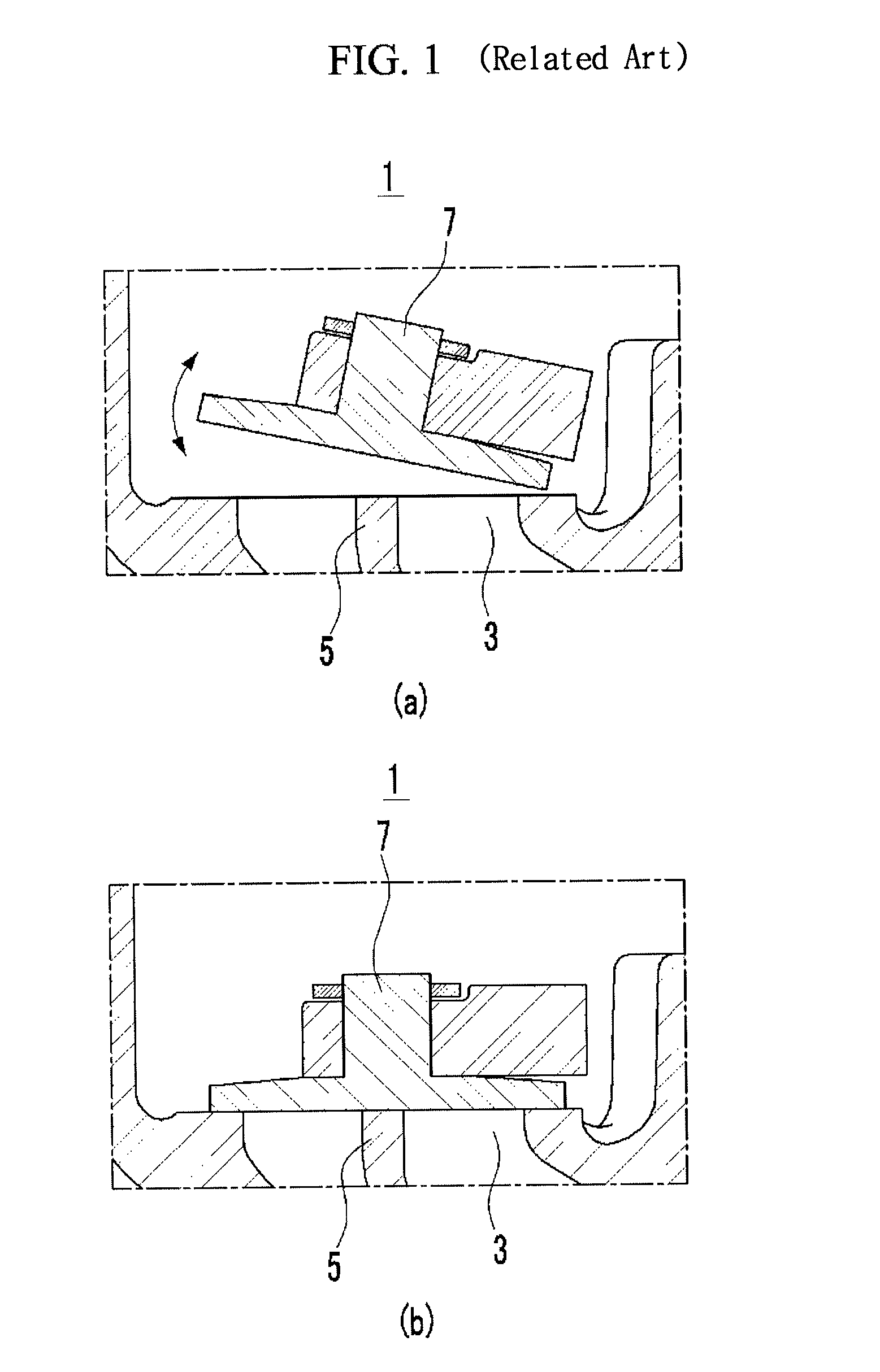
Meanwhile, when an excess boost pressure is generated in an intake manifold, since abnormal combustion or abnormality in the engine is caused, the turbocharger includes a waste gate assembly for suppressing the excess boost pressure depending on a driving condition.
For this reason, it is difficult to actively control a discharge amount of the exhaust gas.

Method used


Image

  • Waste gate assembly for turbocharger
  • Waste gate assembly for turbocharger
  • Waste gate assembly for turbocharger

Examples


Embodiment Construction

[0037]Reference will now be made in detail to various embodiments of the present invention(s), examples of which are illustrated in the accompanying drawings and described below. While the invention(s) will be described in conjunction with exemplary embodiments, it will be understood that present description is not intended to limit the invention(s) to those exemplary embodiments. On the contrary, the invention(s) is / are intended to cover not only the exemplary embodiments, but also various alternatives, modifications, equivalents and other embodiments, which may be included within the spirit and scope of the invention as defined by the appended claims.

[0038]Unrelated parts will be omitted to clearly describe the present invention, and throughout the specification, the same or similar constituent elements will be assigned the same reference numeral. The size and thickness of each configuration shown in the drawings are arbitrarily shown for understanding and ease of description, but...


PUM


Abstract

Disclosed is a waste gate assembly for a turbocharger that is provided at a side of a turbine into which an exhaust gas is introduced, and bypasses some of the exhaust gas introduced into the turbine to an outside. The waste gate assembly may include a boss that has a hole for discharging the exhaust gas and is provided at a waste gate main body, a valve that is provided to spherically come in contact with a valve mounting surface of the boss and selectively opens or closes the hole of the boss, and an actuator that is connected to the valve, and provides a rotational force to the valve.

Description

CROSS-REFERENCE TO RELATED APPLICATION[0001]The present application claims priority of Korean Patent Application Number 10-2013-0129961 filed on Oct. 30, 2013, the entire contents of which application are incorporated herein for all purposes by this reference.BACKGROUND OF INVENTION[0002]1. Field of Invention[0003]The present invention relates to a turbocharger system, and more particularly, to a waste gate assembly for controlling flow of an exhaust gas depending on a driving condition of an engine.[0004]2. Description of Related Art[0005]In general, a turbocharger is a device that supercharges air for combustion for increasing combustion efficiency of an engine, and is mostly applied to a diesel engine. In recent years, the turbocharger has been applied to a gasoline engine.[0006]The turbocharger includes a turbine that is rotated by an exhaust gas, and a compressor that compresses intake air by being rotated by the turbine, and has a structure in which the turbine and the compres...

Claims


Application Information

Patent Timeline
Patent Type & Authority Applications(United States)
IPC IPC(8): F01D17/10F02B37/18
CPCF01D17/105F05D2220/40F02B37/186F02B37/183Y02T10/12F02B37/12F02B37/18
Inventor JUNG, KYUNG-JAELEE, SEUNG YEONKIM, KWANG HWANLEE, GIL-BEOMPARK, JUN GWANYANG, SUNG-JINPARK, UI YEONJIN, KYUNG-WOOK
Owner HYUNDAI MOTOR CO LTD
Learn More